Installation Information
1.Use Class 1 wiring methods (as defined by the NEC) for interface wiring up to 30V. The wire should be rated at 24V, 1A minimum.
2.Use Class 2 wiring methods (as defined by the NEC) for interface wiring from 30 to 600V.
3.When installing external interface wiring (for example, building alarm, relay output, battery breaker trip, and
4.When installing internal interface wiring to
5.All building alarm inputs or remote features require an isolated
6.The building alarms can be programmed to display the alarm functional name.
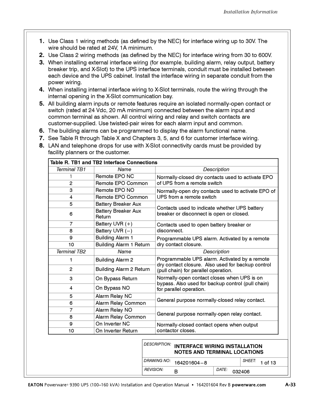
7.See Table R through Table X and Chapters 3, 5, and 6 for customer interface wiring.
8.LAN and telephone drops for use with
|
| Table R. TB1 and TB2 Interface Connections |
|
|
|
|
|
|
|
| |||
|
|
|
|
|
|
|
|
|
|
|
| ||
|
| Terminal TB1 | Name |
|
| Description |
|
|
|
|
| ||
|
| 1 | Remote EPO NC |
|
|
| |||||||
|
| 2 | Remote EPO Common | of UPS from a remote switch |
|
|
|
|
| ||||
|
| 3 | Remote EPO NO |
|
|
| |||||||
|
| 4 | Remote EPO Common | UPS from a remote switch |
|
|
|
|
| ||||
|
| 5 | Battery Breaker Aux | Contacts used to indicate whether UPS battery |
|
|
| ||||||
|
|
| Battery Breaker Aux |
|
|
| |||||||
|
| 6 | breaker or disconnect is open or closed. |
|
|
| |||||||
| Return |
|
|
| |||||||||
|
|
|
|
|
|
|
|
|
|
|
| ||
|
|
|
|
|
|
| |||||||
|
| 7 | Battery UVR (+) | Contacts used to open battery breaker or |
|
|
| ||||||
|
| 8 | Battery UVR | disconnect. |
|
|
|
|
|
|
| ||
|
| 9 | Building Alarm 1 | Programmable UPS alarm. Activated by a remote |
|
|
| ||||||
|
| 10 | Building Alarm 1 Return | dry contact closure. |
|
|
|
|
| ||||
|
| Terminal TB2 | Name |
|
| Description |
|
|
|
|
| ||
|
| 1 | Building Alarm 2 | Programmable UPS alarm. Activated by a remote |
|
|
| ||||||
|
|
|
|
| dry contact closure. Also used for backup control |
|
|
| |||||
|
| 2 | Building Alarm 2 Return |
|
|
| |||||||
| (pull chain) for parallel operation. |
|
|
|
|
| |||||||
|
| 3 | On Bypass Return |
|
|
| |||||||
|
|
|
|
| bypass. Also used for backup control (pull chain) |
|
|
| |||||
|
| 4 | On Bypass NO |
|
|
| |||||||
| for parallel operation. |
|
|
|
|
| |||||||
|
|
|
|
|
|
|
|
|
|
|
| ||
|
| 5 | Alarm Relay NC | General purpose |
|
|
| ||||||
|
| 6 | Alarm Relay Common |
|
|
| |||||||
|
|
|
|
|
|
|
|
|
| ||||
|
| 7 | Alarm Relay NO | General purpose |
|
|
| ||||||
|
| 8 | Alarm Relay Common |
|
|
| |||||||
|
|
|
|
|
|
|
|
|
| ||||
|
| 9 | On Inverter NC |
|
|
| |||||||
|
| 10 | On Inverter Return | contactor closes. |
|
|
|
|
|
|
| ||
|
|
|
|
|
|
|
|
|
|
|
|
|
|
|
|
|
| DESCRIPTION: INTERFACE WIRING INSTALLATION |
|
|
| ||||||
|
|
|
|
|
| NOTES AND TERMINAL LOCATIONS |
|
|
| ||||
|
|
|
|
|
|
|
|
|
|
|
|
| |
|
|
|
| DRAWING NO: |
|
| SHEET: 1 of 13 |
|
|
| |||
|
|
|
| REVISION: | B |
| DATE: | 032406 |
|
|
| ||
|
|
|
|
|
|
|
|
|
|
|
|
|
|
| EATON Powerware® 9390 UPS | 164201604 Rev B powerware.com | |||||||||||