Installation Information
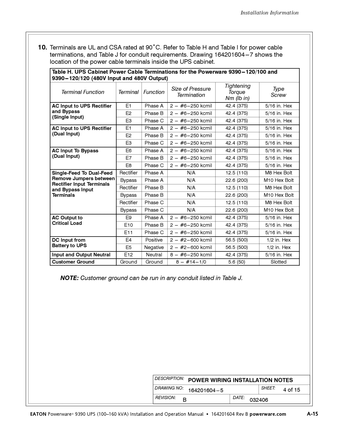
10.Terminals are UL and CSA rated at 90˚C. Refer to Table H and Table I for power cable terminations, and Table J for conduit requirements. Drawing
Table H. UPS Cabinet Power Cable Terminations for the Powerware
Terminal Function | Terminal | Function | Size of Pressure | Tightening | Type | |||
Torque | ||||||||
| Termination | Screw | ||||||
|
|
|
| Nm (lb in) | ||||
|
|
|
|
|
| |||
|
|
|
|
|
|
|
| |
AC Input to UPS Rectifier | E1 | Phase A | 2 | 42.4 | (375) | 5/16 in. Hex | ||
and Bypass |
|
|
|
|
|
|
| |
E2 | Phase B | 2 | 42.4 | (375) | 5/16 in. Hex | |||
(Single Input) | ||||||||
|
|
|
|
|
|
| ||
E3 | Phase C | 2 | 42.4 | (375) | 5/16 in. Hex | |||
| ||||||||
|
|
|
|
|
|
|
| |
AC Input to UPS Rectifier | E1 | Phase A | 2 | 42.4 | (375) | 5/16 in. Hex | ||
(Dual Input) |
|
|
|
|
|
|
| |
E2 | Phase B | 2 | 42.4 | (375) | 5/16 in. Hex | |||
| ||||||||
|
|
|
|
|
|
|
| |
| E3 | Phase C | 2 | 42.4 | (375) | 5/16 in. Hex | ||
|
|
|
|
|
|
|
| |
AC Input To Bypass | E6 | Phase A | 2 | 42.4 | (375) | 5/16 in. Hex | ||
(Dual Input) |
|
|
|
|
|
|
| |
E7 | Phase B | 2 | 42.4 | (375) | 5/16 in. Hex | |||
| ||||||||
|
|
|
|
|
|
|
| |
| E8 | Phase C | 2 | 42.4 | (375) | 5/16 in. Hex | ||
|
|
|
|
|
|
|
| |
Rectifier | Phase A |
| N/A | 12.5 | (110) | M8 Hex Bolt | ||
Remove Jumpers between |
|
|
|
|
|
|
| |
Bypass | Phase A |
| N/A | 22.6 | (200) | M10 Hex Bolt | ||
Rectifier Input Terminals |
|
|
|
|
|
|
| |
Rectifier | Phase B |
| N/A | 12.5 | (110) | M8 Hex Bolt | ||
and Bypass Input |
| |||||||
|
|
|
|
|
|
| ||
Terminals | Bypass | Phase B |
| N/A | 22.6 | (200) | M10 Hex Bolt | |
|
|
|
|
|
|
|
| |
| Rectifier | Phase C |
| N/A | 12.5 | (110) | M8 Hex Bolt | |
|
|
|
|
|
|
|
| |
| Bypass | Phase C |
| N/A | 22.6 | (200) | M10 Hex Bolt | |
|
|
|
|
|
|
|
| |
AC Output to | E9 | Phase A | 2 | 42.4 | (375) | 5/16 in. Hex | ||
Critical Load |
|
|
|
|
|
|
| |
E10 | Phase B | 2 | 42.4 | (375) | 5/16 in. Hex | |||
| ||||||||
|
|
|
|
|
|
|
| |
| E11 | Phase C | 2 | 42.4 | (375) | 5/16 in. Hex | ||
|
|
|
|
|
|
|
| |
DC Input from | E4 | Positive | 2 | 56.5 | (500) | 1/2 in. Hex | ||
Battery to UPS |
|
|
|
|
|
|
| |
E5 | Negative | 2 | 56.5 | (500) | 1/2 in. Hex | |||
| ||||||||
|
|
|
|
|
|
|
| |
Input and Output Neutral | E12 | Neutral | 8 | 42.4 | (375) | 5/16 in. Hex | ||
Customer Ground | Ground | Ground |
| 8 | 5.6 | (50) | Slotted | |
NOTE: Customer ground can be run in any conduit listed in Table J.
|
| DESCRIPTION: | POWER WIRING INSTALLATION NOTES |
|
|
| |||
|
|
|
|
|
|
|
|
|
|
|
| DRAWING NO: |
|
| SHEET: 4 of 15 |
|
|
| |
|
| REVISION: B |
| DATE: | 032406 |
|
|
| |
|
|
|
|
|
|
|
|
|
|
| EATON Powerware® 9390 UPS | ||||||||