Reheat Mode Diagnostic Help
The status of reheat mode sensor inputs may be viewed within the display Inputs menu. The status of reheat mode outputs may be viewed within the display Outputs or Run Status→COOL menus. Additional diagnostic help, including status of circuit reheat temperature limit lockouts may be viewed within the
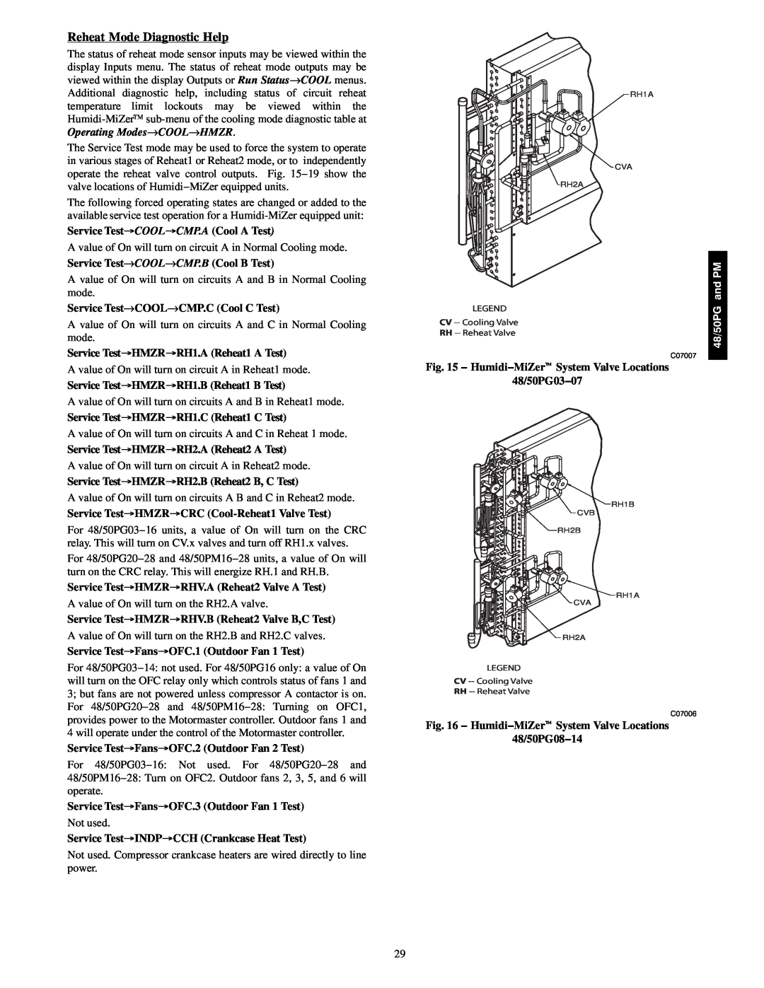
The Service Test mode may be used to force the system to operate in various stages of Reheat1 or Reheat2 mode, or to independently operate the reheat valve control outputs. Fig. 15−19 show the valve locations of Humidi−MiZer equipped units.
The following forced operating states are changed or added to the available service test operation for a
Service Test"COOL"CMP.A (Cool A Test)
A value of On will turn on circuit A in Normal Cooling mode. Service Test→COOL→CMP.B (Cool B Test)
A value of On will turn on circuits A and B in Normal Cooling mode.
Service Test→COOL→CMP.C (Cool C Test)
A value of On will turn on circuits A and C in Normal Cooling mode.
Service Test"HMZR"RH1.A (Reheat1 A Test)
A value of On will turn on circuit A in Reheat1 mode.
Service Test"HMZR"RH1.B (Reheat1 B Test)
A value of On will turn on circuits A and B in Reheat1 mode.
Service Test"HMZR"RH1.C (Reheat1 C Test)
A value of On will turn on circuits A and C in Reheat 1 mode.
Service Test"HMZR"RH2.A (Reheat2 A Test)
A value of On will turn on circuit A in Reheat2 mode.
Service Test"HMZR"RH2.B (Reheat2 B, C Test)
A value of On will turn on circuits A B and C in Reheat2 mode.
Service Test"HMZR"CRC (Cool-Reheat1 Valve Test)
For 48/50PG03−16 units, a value of On will turn on the CRC relay. This will turn on CV.x valves and turn off RH1.x valves.
For 48/50PG20−28 and 48/50PM16−28 units, a value of On will turn on the CRC relay. This will energize RH.1 and RH.B.
Service Test"HMZR"RHV.A (Reheat2 Valve A Test)
A value of On will turn on the RH2.A valve.
Service Test"HMZR"RHV.B (Reheat2 Valve B,C Test)
A value of On will turn on the RH2.B and RH2.C valves.
Service Test"Fans"OFC.1 (Outdoor Fan 1 Test)
For 48/50PG03−14: not used. For 48/50PG16 only: a value of On will turn on the OFC relay only which controls status of fans 1 and 3; but fans are not powered unless compressor A contactor is on. For 48/50PG20−28 and 48/50PM16−28: Turning on OFC1, provides power to the Motormaster controller. Outdoor fans 1 and 4 will operate under the control of the Motormaster controller.
Service Test"Fans"OFC.2 (Outdoor Fan 2 Test)
For 48/50PG03−16: Not used. For 48/50PG20−28 and
48/50PM16−28: Turn on OFC2. Outdoor fans 2, 3, 5, and 6 will operate.
Service Test"Fans"OFC.3 (Outdoor Fan 1 Test)
Not used.
Service Test"INDP"CCH (Crankcase Heat Test)
Not used. Compressor crankcase heaters are wired directly to line power.
RH1A
CVA
RH2A
LEGEND
CV
RH
C07007
Fig. 15 − Humidi−MiZert System Valve Locations
48/50PG03−07
RH1B
CVB
RH2B
RH1A
CVA
RH2A
LEGEND
CV
RH
C07006
Fig. 16 − Humidi−MiZert System Valve Locations
48/50PG08−14
48/50PG and PM
29