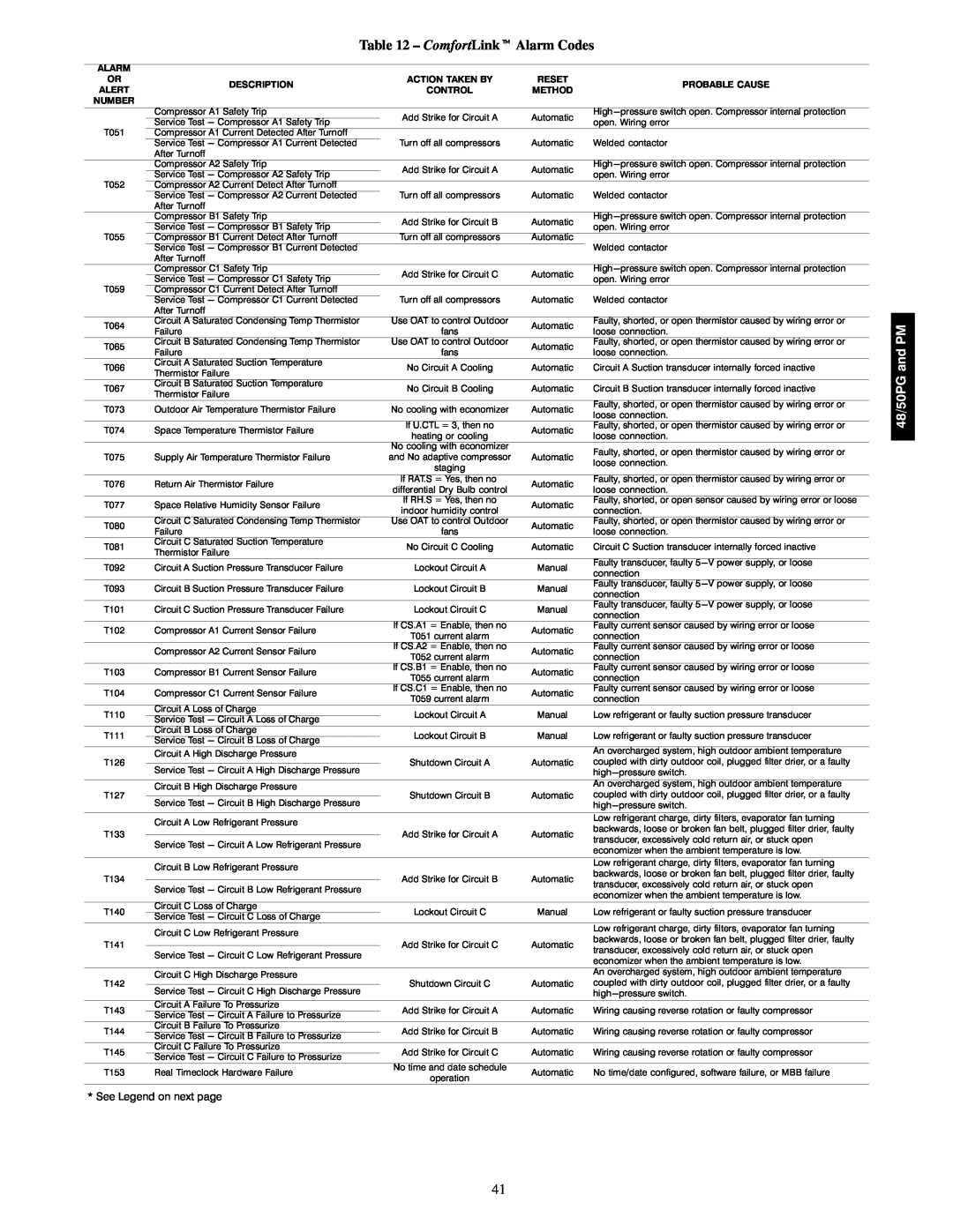
Table 12 – ComfortLinkt Alarm Codes
ALARM |
| |
OR | DESCRIPTION | |
ALERT | ||
| ||
NUMBER |
| |
| Compressor A1 Safety Trip | |
| Service Test - Compressor A1 Safety Trip | |
T051 | Compressor A1 Current Detected After Turnoff | |
| Service Test - Compressor A1 Current Detected | |
| After Turnoff | |
| Compressor A2 Safety Trip | |
| Service Test - Compressor A2 Safety Trip | |
T052 | Compressor A2 Current Detect After Turnoff | |
| Service Test - Compressor A2 Current Detected | |
| After Turnoff | |
| Compressor B1 Safety Trip | |
| Service Test - Compressor B1 Safety Trip | |
T055 | Compressor B1 Current Detect After Turnoff | |
| Service Test - Compressor B1 Current Detected | |
| After Turnoff | |
| Compressor C1 Safety Trip | |
| Service Test - Compressor C1 Safety Trip | |
T059 | Compressor C1 Current Detect After Turnoff | |
| Service Test - Compressor C1 Current Detected | |
| After Turnoff | |
T064 | Circuit A Saturated Condensing Temp Thermistor | |
Failure | ||
| ||
T065 | Circuit B Saturated Condensing Temp Thermistor | |
Failure | ||
| ||
T066 | Circuit A Saturated Suction Temperature | |
Thermistor Failure | ||
| ||
T067 | Circuit B Saturated Suction Temperature | |
Thermistor Failure | ||
| ||
T073 | Outdoor Air Temperature Thermistor Failure | |
T074 | Space Temperature Thermistor Failure | |
T075 | Supply Air Temperature Thermistor Failure | |
T076 | Return Air Thermistor Failure | |
T077 | Space Relative Humidity Sensor Failure | |
T080 | Circuit C Saturated Condensing Temp Thermistor | |
Failure | ||
| ||
T081 | Circuit C Saturated Suction Temperature | |
Thermistor Failure | ||
| ||
T092 | Circuit A Suction Pressure Transducer Failure | |
T093 | Circuit B Suction Pressure Transducer Failure | |
T101 | Circuit C Suction Pressure Transducer Failure | |
T102 | Compressor A1 Current Sensor Failure | |
| Compressor A2 Current Sensor Failure | |
T103 | Compressor B1 Current Sensor Failure | |
T104 | Compressor C1 Current Sensor Failure | |
T110 | Circuit A Loss of Charge | |
Service Test - Circuit A Loss of Charge | ||
| ||
T111 | Circuit B Loss of Charge | |
Service Test - Circuit B Loss of Charge | ||
| ||
T126 | Circuit A High Discharge Pressure | |
Service Test - Circuit A High Discharge Pressure | ||
| ||
T127 | Circuit B High Discharge Pressure | |
Service Test - Circuit B High Discharge Pressure | ||
| ||
| Circuit A Low Refrigerant Pressure | |
T133 |
| |
| Service Test - Circuit A Low Refrigerant Pressure | |
| Circuit B Low Refrigerant Pressure | |
T134 |
| |
| Service Test - Circuit B Low Refrigerant Pressure | |
T140 | Circuit C Loss of Charge | |
Service Test - Circuit C Loss of Charge | ||
| ||
| Circuit C Low Refrigerant Pressure | |
T141 |
| |
| Service Test - Circuit C Low Refrigerant Pressure | |
T142 | Circuit C High Discharge Pressure | |
Service Test - Circuit C High Discharge Pressure | ||
| ||
T143 | Circuit A Failure To Pressurize | |
Service Test - Circuit A Failure to Pressurize | ||
| ||
T144 | Circuit B Failure To Pressurize | |
Service Test - Circuit B Failure to Pressurize | ||
| ||
T145 | Circuit C Failure To Pressurize | |
Service Test - Circuit C Failure to Pressurize | ||
| ||
T153 | Real Timeclock Hardware Failure |
* See Legend on next page
ACTION TAKEN BY
CONTROL
Add Strike for Circuit A
Turn off all compressors
Add Strike for Circuit A
Turn off all compressors
Add Strike for Circuit B
Turn off all compressors
Add Strike for Circuit C
Turn off all compressors
Use OAT to control Outdoor
fans
Use OAT to control Outdoor
fans
No Circuit A Cooling
No Circuit B Cooling
No cooling with economizer
If U.CTL = 3, then no
heating or cooling
No cooling with economizer and No adaptive compressor staging
If RAT.S = Yes, then no differential Dry Bulb control If RH.S = Yes, then no indoor humidity control Use OAT to control Outdoor fans
No Circuit C Cooling
Lockout Circuit A
Lockout Circuit B
Lockout Circuit C
If CS.A1 = Enable, then no
T051 current alarm
If CS.A2 = Enable, then no
T052 current alarm
If CS.B1 = Enable, then no
T055 current alarm
If CS.C1 = Enable, then no
T059 current alarm
Lockout Circuit A
Lockout Circuit B
Shutdown Circuit A
Shutdown Circuit B
Add Strike for Circuit A
Add Strike for Circuit B
Lockout Circuit C
Add Strike for Circuit C
Shutdown Circuit C
Add Strike for Circuit A
Add Strike for Circuit B
Add Strike for Circuit C
No time and date schedule
operation
RESET | PROBABLE CAUSE | |
METHOD | ||
| ||
Automatic | ||
open. Wiring error | ||
| ||
Automatic | Welded contactor | |
Automatic | ||
open. Wiring error | ||
| ||
Automatic | Welded contactor | |
Automatic | ||
open. Wiring error | ||
| ||
Automatic |
| |
| Welded contactor | |
Automatic | ||
open. Wiring error | ||
| ||
Automatic | Welded contactor | |
Automatic | Faulty, shorted, or open thermistor caused by wiring error or | |
loose connection. | ||
| ||
Automatic | Faulty, shorted, or open thermistor caused by wiring error or | |
loose connection. | ||
| ||
Automatic | Circuit A Suction transducer internally forced inactive | |
Automatic | Circuit B Suction transducer internally forced inactive | |
Automatic | Faulty, shorted, or open thermistor caused by wiring error or | |
loose connection. | ||
| ||
Automatic | Faulty, shorted, or open thermistor caused by wiring error or | |
loose connection. | ||
| ||
Automatic | Faulty, shorted, or open thermistor caused by wiring error or | |
loose connection. | ||
| ||
Automatic | Faulty, shorted, or open thermistor caused by wiring error or | |
loose connection. | ||
| ||
Automatic | Faulty, shorted, or open sensor caused by wiring error or loose | |
connection. | ||
| ||
Automatic | Faulty, shorted, or open thermistor caused by wiring error or | |
loose connection. | ||
| ||
Automatic | Circuit C Suction transducer internally forced inactive | |
Manual | Faulty transducer, faulty | |
connection | ||
| ||
Manual | Faulty transducer, faulty | |
connection | ||
| ||
Manual | Faulty transducer, faulty | |
connection | ||
| ||
Automatic | Faulty current sensor caused by wiring error or loose | |
connection | ||
| ||
Automatic | Faulty current sensor caused by wiring error or loose | |
connection | ||
| ||
Automatic | Faulty current sensor caused by wiring error or loose | |
connection | ||
| ||
Automatic | Faulty current sensor caused by wiring error or loose | |
connection | ||
| ||
Manual | Low refrigerant or faulty suction pressure transducer | |
Manual | Low refrigerant or faulty suction pressure transducer | |
| An overcharged system, high outdoor ambient temperature | |
Automatic | coupled with dirty outdoor coil, plugged filter drier, or a faulty | |
| ||
| An overcharged system, high outdoor ambient temperature | |
Automatic | coupled with dirty outdoor coil, plugged filter drier, or a faulty | |
| ||
| Low refrigerant charge, dirty filters, evaporator fan turning | |
Automatic | backwards, loose or broken fan belt, plugged filter drier, faulty | |
transducer, excessively cold return air, or stuck open | ||
| ||
| economizer when the ambient temperature is low. | |
| Low refrigerant charge, dirty filters, evaporator fan turning | |
Automatic | backwards, loose or broken fan belt, plugged filter drier, faulty | |
transducer, excessively cold return air, or stuck open | ||
| ||
| economizer when the ambient temperature is low. | |
Manual | Low refrigerant or faulty suction pressure transducer | |
| Low refrigerant charge, dirty filters, evaporator fan turning | |
Automatic | backwards, loose or broken fan belt, plugged filter drier, faulty | |
transducer, excessively cold return air, or stuck open | ||
| ||
| economizer when the ambient temperature is low. | |
| An overcharged system, high outdoor ambient temperature | |
Automatic | coupled with dirty outdoor coil, plugged filter drier, or a faulty | |
| ||
Automatic | Wiring causing reverse rotation or faulty compressor | |
Automatic | Wiring causing reverse rotation or faulty compressor | |
Automatic | Wiring causing reverse rotation or faulty compressor | |
Automatic | No time/date configured, software failure, or MBB failure |
48/50PG and PM
41