Phase Loss Protection
The phase loss protection option will monitor the
Phase Reversal Protection
If the control senses an incorrect phase relationship, the relay (K1) will be
Phase Loss Protection
If the reverse rotation board senses any one of the three phase inputs has no AC voltage, the relay will be de−energized (opening its contact). This protection is always active as long as
A red LED is provided to indicate the function of the board. See the table below.
LED STATUS | FUNCTION |
On Continuously | Relay contact closed (normal operation). |
| Relay contact open (phase loss or phase |
Blinking | reversal has occurred) — No power will be |
| supplied to the control system. |
Off | 24 vac control power not present (off). |
Thermistor Troubleshooting
The electronic control uses thermistors to sense temperatures used to control operation of the unit. Resistances at various temperatures are listed in Table 20 and 21. Thermistor pin connection points are shown in the Major System Components section. The general locations of the thermistors are shown the Major System Components section.
Air Temperatures
Air temperatures are measured with 10
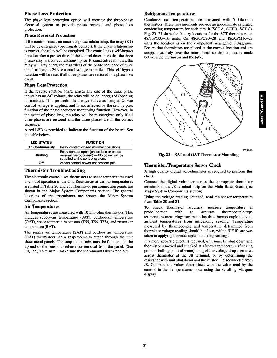
The supply air temperature (SAT) and outdoor air temperature (OAT) thermistors use a
Refrigerant Temperatures
Condenser coil temperatures are measured with 5
48/50PG and PM
C07015
Fig. 22 − SAT and OAT Thermistor Mounting
Thermistor/Temperature Sensor Check
A high quality digital
Connect the digital voltmeter across the appropriate thermistor terminals at the J8 terminal strip on the Main Base Board (see Major System Components section).
Using the voltage reading obtained, read the sensor temperature from Table 20 and 21.
To check thermistor accuracy, measure temperature at
probe location with an accurate
If a more accurate check is required, unit must be shut down and thermistor removed and checked at a known temperature (freezing point or boiling point of water) using either voltage drop measured across thermistor at the J8 terminal, or by determining the resistance with unit shut down and thermistor disconnected from J8. Compare the values determined with the value read by the control in the Temperatures mode using the Scrolling Marquee display.
51