48/50PG and PM
Alert Code T415 − IAQ Input Out of Range
This alert occurs when the IAQ input (on ECB) is less than 3.5 mA and the sensor is configured as installed. IAQ operation will be disabled. Check sensor and wiring. This alert clears automatically.
Alert Code T416 − OAQ Input Out of Range
This alert occurs when the OAQ input (on ECB) is less than 3.5 mA and the sensor is configured as installed. OAQ operation will be disabled. Check sensor and wiring. This alert clears automatically.
Alert Code T418
There are 4 different alerts under this one alert code. Pressing enter and esc on the marquee or navigator to expand the T418 alert will show you one of the below alerts. All these alerts are generated by the OAU device and reported to the MBB. These alerts can only occur if the Outdoor Air Unit Type (Configuration → OAU → OA.TY) is not set to 0. Control action is only taken on the OAU side and these alerts will reset automatically when the OAU clears
them. Refer to the EnergyXv2 Supplement Installation Instructions for more information on these alarms.
OAU Motor Failure
This alert occurs when the OAU Motor Failure Alarm (Operating Modes → OAU → ALM.1) is on. This is usually due to motor status reporting a failure on the OAU.
OAU Dirty Filter
This alert occurs when the OAU Dirty Filter Alarm (Operating Modes → OAU → ALM.2) is on. This is usually due to filter status reporting a dirty filter on the OAU.
OAU Low CFM
This alert occurs when the OAU Low CFM Alarm (Operating Modes → OAU → ALM.3) is on. This is usually due to OAU not capable of achieving proper CFM.
OAU General Alarm
This alert occurs when the OAU Alarm (Operating Modes → OAU → ALM.4) is on. Refer to the specific OAU documentation for details.
Control Module Communication
Red LED
Proper operation of the MBB and ECB control boards can be visually checked by looking at the red status LEDs. When operating correctly, the red status LEDs should blink in unison at a rate of once every 2 seconds. If the red LED on the ECB is not blinking, check the DIP switch positions on the board. If the red LEDs are not blinking in unison, verify that correct power is being supplied to all modules. A blinking red LED at the rate of once per second means that software is not loaded on the board. Also, be sure that the board is supplied with the current software. If necessary, reload current software. A board LED that is lit continuously should be replaced.
Green LED
The MBB and ECB each have one green LED. The Local Equipment Network (LEN) LED should always be blinking whenever power is on. If LEN LED is not blinking, check LEN connections for potential communication errors (MBB J3, J4, and J5). Communication between modules is accomplished by a
Yellow LED
The MBB has one yellow LED which is used to indicate CCN communication activity. The Carrier Comfort Network (CCN) LED will blink during times of network communication.
Communication Failures
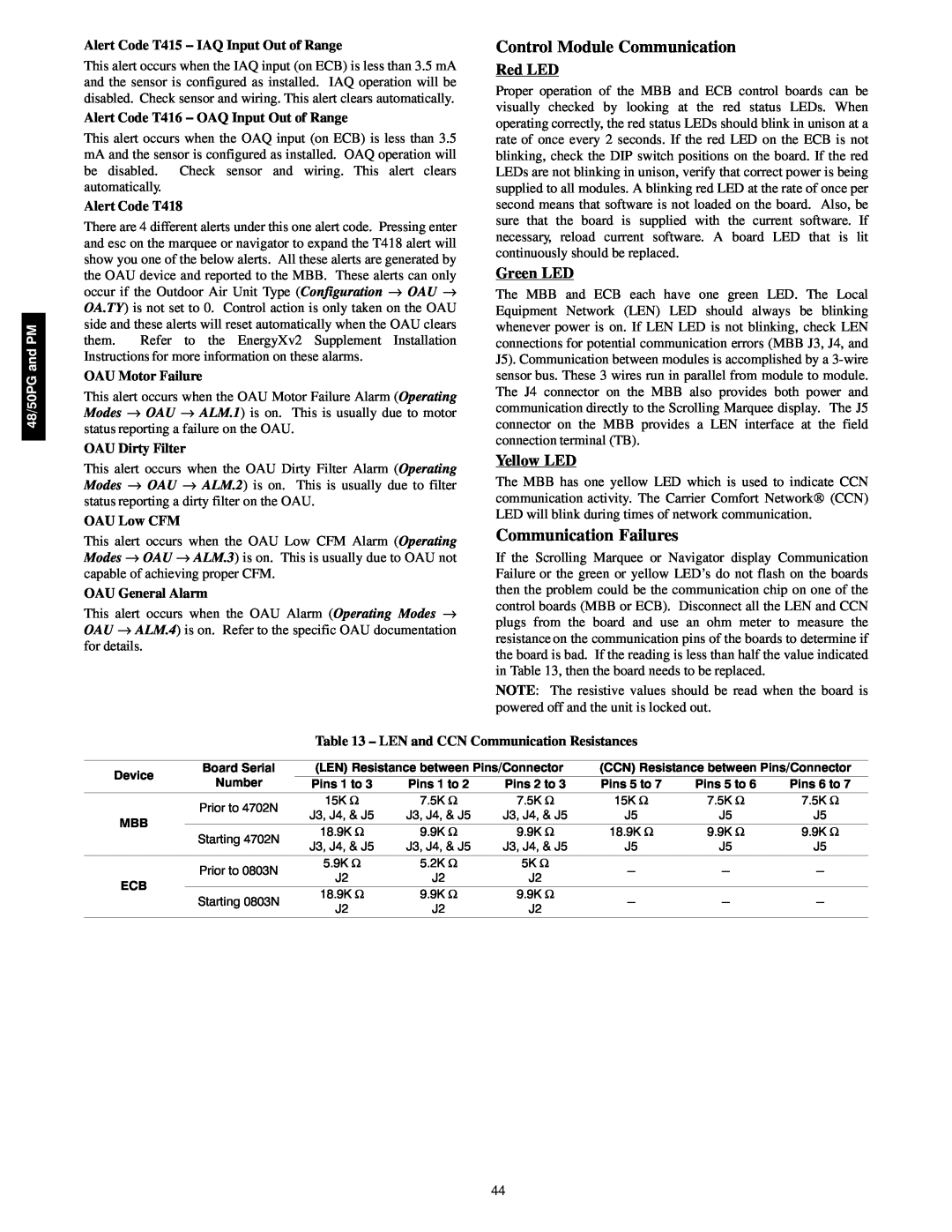
If the Scrolling Marquee or Navigator display Communication Failure or the green or yellow LED’s do not flash on the boards then the problem could be the communication chip on one of the control boards (MBB or ECB). Disconnect all the LEN and CCN plugs from the board and use an ohm meter to measure the resistance on the communication pins of the boards to determine if the board is bad. If the reading is less than half the value indicated in Table 13, then the board needs to be replaced.
NOTE: The resistive values should be read when the board is powered off and the unit is locked out.
Table 13 – LEN and CCN Communication Resistances
Device | Board Serial | (LEN) Resistance between Pins/Connector | (CCN) Resistance between Pins/Connector | |||||||
Number | Pins 1 to 3 | Pins 1 to 2 | Pins 2 to 3 | Pins 5 to 7 | Pins 5 to 6 | Pins 6 to 7 | ||||
| ||||||||||
| Prior to 4702N | 15K Ω | 7.5K | Ω | 7.5K Ω | 15K Ω | 7.5K | Ω | 7.5K Ω | |
| J3, J4, & J5 | J3, J4, & J5 | J3, J4, & J5 | J5 | J5 |
| J5 | |||
MBB |
|
| ||||||||
| 18.9K Ω | 9.9K | Ω | 9.9K Ω | 18.9K Ω | 9.9K | Ω | 9.9K Ω | ||
| Starting 4702N | |||||||||
| J3, J4, & J5 | J3, J4, & J5 | J3, J4, & J5 | J5 | J5 |
| J5 | |||
|
|
| ||||||||
| Prior to 0803N | 5.9K Ω | 5.2K | Ω | 5K Ω | - | - |
| - | |
| J2 | J2 |
| J2 |
| |||||
ECB |
|
|
|
|
|
| ||||
| 18.9K Ω | 9.9K | Ω | 9.9K Ω |
|
|
|
| ||
| Starting 0803N | - | - |
| - | |||||
| J2 | J2 |
| J2 |
| |||||
|
|
|
|
|
|
| ||||
44