APPENDIX A — LOCAL DISPLAY AND CCN TABLES (CONT)
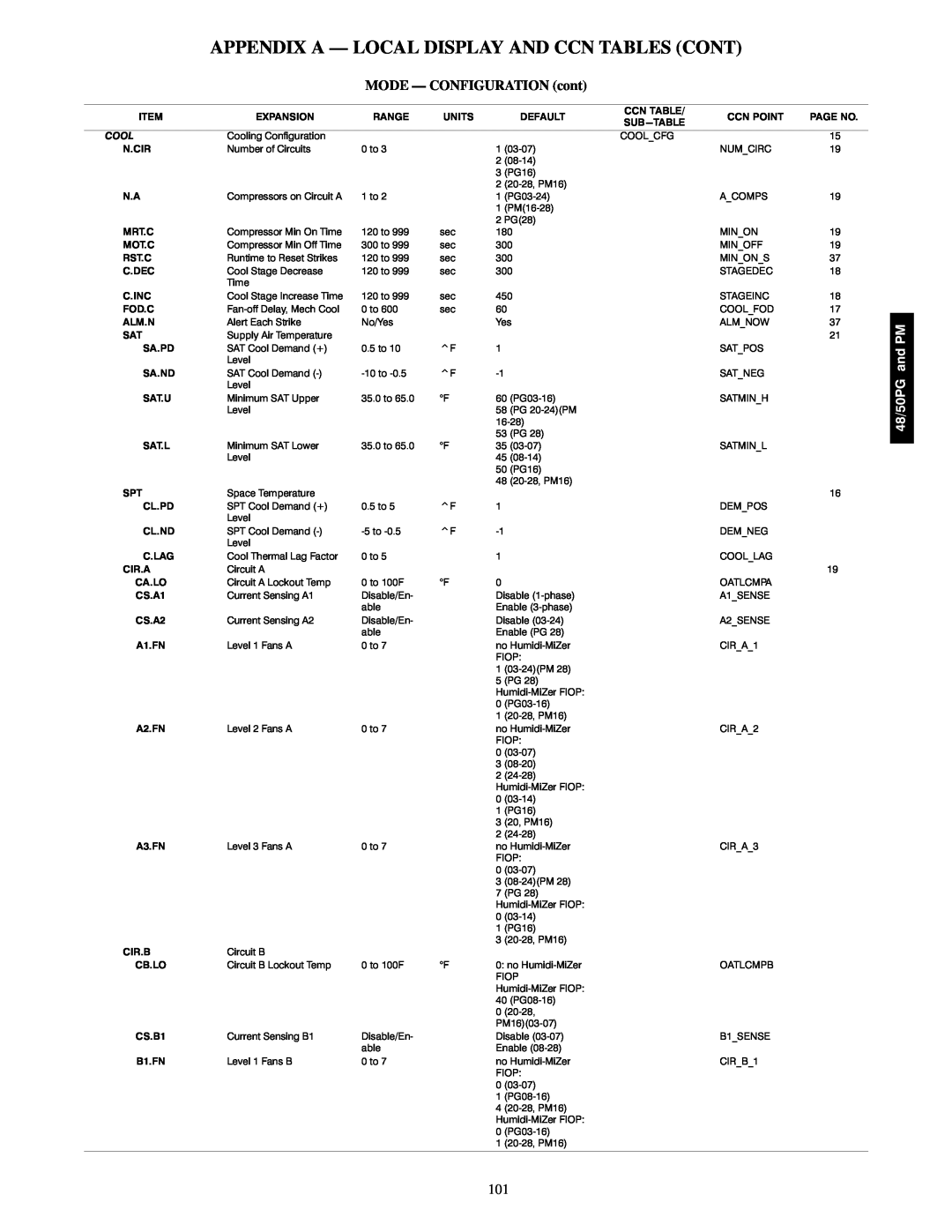
MODE — CONFIGURATION (cont)
ITEM | EXPANSION | RANGE | UNITS |
| DEFAULT |
COOL | Cooling Configuration |
|
|
|
|
N.CIR | Number of Circuits | 0 to 3 |
| 1 | (0307) |
|
|
|
| 2 | (0814) |
|
|
|
| 3 | (PG16) |
|
|
|
| 2 | (2028, PM16) |
N.A | Compressors on Circuit A | 1 to 2 |
| 1 | (PG0324) |
|
|
|
| 1 | (PM(1628) |
|
|
|
| 2 | PG(28) |
MRT.C | Compressor Min On Time | 120 to 999 | sec | 180 | |
MOT.C | Compressor Min Off Time | 300 to 999 | sec | 300 | |
RST.C | Runtime to Reset Strikes | 120 to 999 | sec | 300 | |
C.DEC | Cool Stage Decrease | 120 to 999 | sec | 300 | |
| Time |
|
|
|
|
C.INC | Cool Stage Increase Time | 120 to 999 | sec | 450 | |
FOD.C | Fanoff Delay, Mech Cool | 0 to 600 | sec | 60 | |
ALM.N | Alert Each Strike | No/Yes |
| Yes | |
SAT | Supply Air Temperature |
|
|
|
|
SA.PD | SAT Cool Demand (+) | 0.5 to 10 | ^F | 1 |
|
| Level |
|
|
|
|
SA.ND | SAT Cool Demand () | 10 to 0.5 | ^F | 1 | |
| Level |
|
|
|
|
SAT.U | Minimum SAT Upper | 35.0 to 65.0 | °F | 60 (PG0316) | |
| Level |
|
| 58 (PG 2024)(PM | |
|
|
|
| 1628) | |
|
|
|
| 53 (PG 28) | |
SAT.L | Minimum SAT Lower | 35.0 to 65.0 | °F | 35 (0307) | |
| Level |
|
| 45 (0814) | |
|
|
|
| 50 (PG16) | |
|
|
|
| 48 (2028, PM16) | |
SPT | Space Temperature |
|
|
|
|
CL.PD | SPT Cool Demand (+) | 0.5 to 5 | ^F | 1 |
|
| Level |
|
|
|
|
CL.ND | SPT Cool Demand () | 5 to 0.5 | ^F | 1 | |
| Level |
|
|
|
|
C.LAG | Cool Thermal Lag Factor | 0 to 5 |
| 1 |
|
CIR.A | Circuit A |
|
|
|
|
CA.LO | Circuit A Lockout Temp | 0 to 100F | °F | 0 |
|
CS.A1 | Current Sensing A1 | Disable/En |
| Disable (1phase) | |
|
| able |
| Enable (3phase) | |
CS.A2 | Current Sensing A2 | Disable/En |
| Disable (0324) | |
|
| able |
| Enable (PG 28) | |
A1.FN | Level 1 Fans A | 0 to 7 |
| no HumidiMiZer | |
|
|
|
| FIOP: | |
|
|
|
| 1 | (0324)(PM 28) |
|
|
|
| 5 | (PG 28) |
|
|
|
| HumidiMiZer FIOP: | |
|
|
|
| 0 | (PG0316) |
|
|
|
| 1 | (2028, PM16) |
A2.FN | Level 2 Fans A | 0 to 7 |
| no HumidiMiZer | |
|
|
|
| FIOP: | |
|
|
|
| 0 | (0307) |
|
|
|
| 3 | (0820) |
|
|
|
| 2 | (2428) |
|
|
|
| HumidiMiZer FIOP: | |
|
|
|
| 0 | (0314) |
|
|
|
| 1 | (PG16) |
|
|
|
| 3 | (20, PM16) |
|
|
|
| 2 | (2428) |
A3.FN | Level 3 Fans A | 0 to 7 |
| no HumidiMiZer | |
|
|
|
| FIOP: | |
|
|
|
| 0 | (0307) |
|
|
|
| 3 | (0824)(PM 28) |
|
|
|
| 7 | (PG 28) |
|
|
|
| HumidiMiZer FIOP: | |
|
|
|
| 0 | (0314) |
|
|
|
| 1 | (PG16) |
|
|
|
| 3 | (2028, PM16) |
CIR.B | Circuit B |
|
|
|
|
CB.LO | Circuit B Lockout Temp | 0 to 100F | °F | 0: no HumidiMiZer | |
|
|
|
| FIOP | |
|
|
|
| HumidiMiZer FIOP: | |
|
|
|
| 40 (PG0816) | |
|
|
|
| 0 | (2028, |
|
|
|
| PM16)(0307) | |
CS.B1 | Current Sensing B1 | Disable/En |
| Disable (0307) | |
|
| able |
| Enable (0828) | |
B1.FN | Level 1 Fans B | 0 to 7 |
| no HumidiMiZer | |
|
|
|
| FIOP: | |
|
|
|
| 0 | (0307) |
|
|
|
| 1 | (PG0816) |
|
|
|
| 4 | (2028, PM16) |
|
|
|
| HumidiMiZer FIOP: | |
|
|
|
| 0 | (PG0316) |
|
|
|
| 1 | (2028, PM16) |
CCN TABLE/
COOL_CFG
CCN POINT | PAGE NO. |
15
NUM_CIRC19
A_COMPS19
MIN_ON19
MIN_OFF19
MIN_ON_S37
STAGEDEC18
STAGEINC18
COOL_FOD 17
ALM_NOW37 21
SAT_POS
SAT_NEG
SATMIN_H
SATMIN_L
16
DEM_POS
DEM_NEG
COOL_LAG
19
OATLCMPA
A1_SENSE
A2_SENSE
CIR_A_1
CIR_A_2
CIR_A_3
OATLCMPB
B1_SENSE
CIR_B_1
48/50PG and PM
101