Scrolling Marquee Display
This device is the keypad interface used to access rooftop information, read sensor values, and test the unit. (See Fig. 44.) The Scrolling Marquee display is a
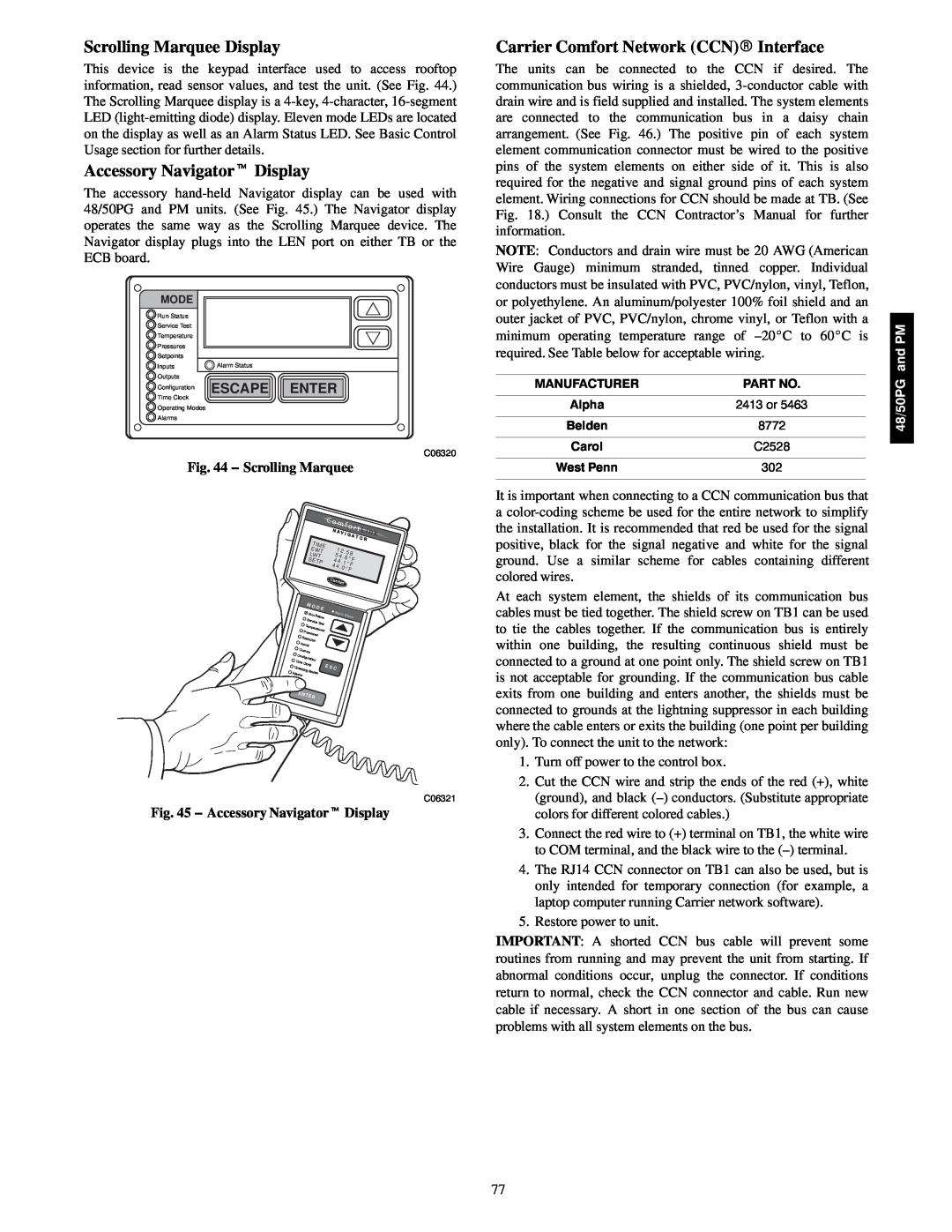
Accessory Navigatort Display
The accessory
MODE |
|
Run Status |
|
Service Test |
|
Temperature |
|
Pressures |
|
Setpoints |
|
Inputs | Alarm Status |
Outputs | ESCAPE ENTER |
Configuration | |
Time Clock |
|
Operating Modes |
|
Alarms |
|
C06320
Fig. 44 − Scrolling Marquee
|
|
|
|
|
|
| C o | m f | o r | t L |
|
| |||||
|
|
|
|
|
|
|
| N | i n | k | |||||||
|
|
|
|
|
|
|
| A V | I | ||||||||
|
|
|
|
|
|
|
|
| G | A T | |||||||
|
| TIME |
|
|
|
|
|
|
|
| O R |
| |||||
|
|
|
| 1 |
|
|
|
|
|
|
|
| |||||
|
| EW | T |
|
|
| 2 . 5 8 |
|
|
| |||||||
|
| L |
|
|
|
| 5 |
|
|
| |||||||
|
| WT |
|
| 4 . | 6 ° | F |
|
|
| |||||||
|
| SE |
|
|
|
|
| 4 |
|
|
|
|
| ||||
|
| TP |
|
| 4 . 1 |
|
|
|
|
| |||||||
|
|
|
|
|
| ° F |
|
|
| ||||||||
|
|
|
|
|
|
|
| 4 4 | . 0 |
|
|
|
| ||||
|
|
|
|
|
|
|
| ° F |
|
|
|
| |||||
|
| M O | D E |
|
|
|
|
|
|
|
|
|
|
|
| ||
|
|
|
|
| Alarm |
|
|
|
|
|
|
| |||||
|
| Run | Status |
|
| Sta | tus |
|
|
| |||||||
|
| Service | Test |
|
|
|
|
|
|
|
|
|
|
|
| ||
| T |
|
|
|
|
|
|
|
|
|
|
|
|
|
|
| |
| P | empera | tures |
|
|
|
|
|
|
|
|
|
|
|
| ||
| ress |
|
|
|
|
|
|
|
|
|
|
|
|
| |||
| Se | ures |
|
|
|
|
|
|
|
|
|
|
|
|
|
| |
| tpoints |
|
|
|
|
|
|
|
|
|
|
|
|
|
|
| |
In |
|
|
|
|
|
|
|
|
|
|
|
|
|
|
| ||
|
|
|
|
|
|
|
|
|
|
|
|
|
|
|
| ||
| puts |
|
|
|
|
|
|
|
|
|
|
|
|
|
|
| |
O |
|
|
|
|
|
|
|
|
|
|
|
|
|
|
|
|
|
| utputs |
|
|
|
|
|
|
|
|
|
|
|
|
|
|
| |
Con |
|
|
|
|
|
|
|
|
|
|
|
|
|
|
|
| |
| figuration |
|
|
|
|
|
|
|
|
|
|
|
|
|
| ||
Time |
|
|
|
|
|
|
|
|
|
|
|
|
|
|
|
| |
Oper | Clock |
|
|
| E | S C |
|
|
|
|
|
|
|
|
| ||
ating M |
|
|
|
|
|
|
|
|
|
|
|
|
|
| |||
Alarms |
| odes |
|
|
|
|
|
|
|
|
|
|
|
|
|
| |
ENT |
|
|
|
|
|
|
|
|
|
|
|
|
|
|
| ||
|
| ER |
|
|
|
|
|
|
|
|
|
|
|
|
|
|
|
C06321
Fig. 45 − Accessory Navigatort Display
Carrier Comfort Network (CCN)R Interface
The units can be connected to the CCN if desired. The communication bus wiring is a shielded,
NOTE: Conductors and drain wire must be 20 AWG (American Wire Gauge) minimum stranded, tinned copper. Individual conductors must be insulated with PVC, PVC/nylon, vinyl, Teflon, or polyethylene. An aluminum/polyester 100% foil shield and an outer jacket of PVC, PVC/nylon, chrome vinyl, or Teflon with a minimum operating temperature range of
MANUFACTURER | PART NO. |
Alpha | 2413 or 5463 |
Belden | 8772 |
Carol | C2528 |
West Penn | 302 |
It is important when connecting to a CCN communication bus that a
At each system element, the shields of its communication bus cables must be tied together. The shield screw on TB1 can be used to tie the cables together. If the communication bus is entirely within one building, the resulting continuous shield must be connected to a ground at one point only. The shield screw on TB1 is not acceptable for grounding. If the communication bus cable exits from one building and enters another, the shields must be connected to grounds at the lightning suppressor in each building where the cable enters or exits the building (one point per building only). To connect the unit to the network:
1.Turn off power to the control box.
2.Cut the CCN wire and strip the ends of the red (+), white (ground), and black
3.Connect the red wire to (+) terminal on TB1, the white wire to COM terminal, and the black wire to the
4.The RJ14 CCN connector on TB1 can also be used, but is only intended for temporary connection (for example, a laptop computer running Carrier network software).
5.Restore power to unit.
IMPORTANT: A shorted CCN bus cable will prevent some routines from running and may prevent the unit from starting. If abnormal conditions occur, unplug the connector. If conditions return to normal, check the CCN connector and cable. Run new cable if necessary. A short in one section of the bus can cause problems with all system elements on the bus.
48/50PG and PM
77