Manuals
/
Carrier
/
Household Appliance
/
Air Conditioner
Carrier
48/50PG C03-14, 48/50PM C16-28
manual
48/50PG and PM, C101252
Models:
48/50PM C16-28
48/50PG C03-14
1
70
188
188
Download
188 pages
11.12 Kb
67
68
69
70
71
72
73
74
Troubleshooting
Alarm Output
Internal Wiring
Display Configuration
Reheat Mode Diagnostic Help
Accessory Navigator Display
Condenser-FanAdjustment Fig
Phase Loss Protection
Setting Up the System
Checklist
Page 70
Image 70
48/50PG and PM
C101252
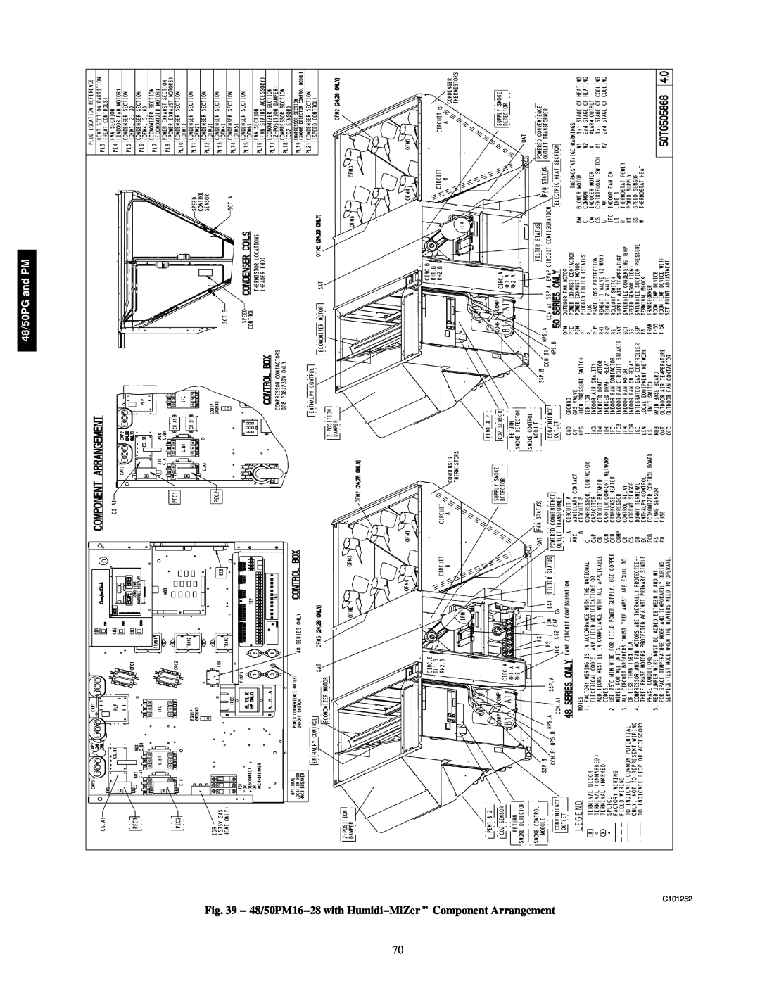
Fig. 39 − 48/50PM16−28 with Humidi−MiZer
t
Component Arrangement
70
Page 69
Page 71
Page 70
Image 70
Page 69
Page 71
Contents
and Troubleshooting Instructions
TABLE OF CONTENTS
Controls, Start-Up,Operation, Service
48/50PG C03-14 48/50PM C16-28
ELECTRICAL SHOCK HAZARD
SAFETY CONSIDERATIONS
UNIT DAMAGE HAZARD
ComfortLink Control
GENERAL
BASIC CONTROL USAGE
Scrolling Marquee
Operation
Accessory Navigator Display
Fig. 2 − Accessory Navigator Display
System Pilott and Touch Pilot Devices
Generic Status Display Table
Force Hierarchy
Fig. 3 − System Pilott User Interface
Internal Wiring
Refrigerant Service Ports
Power Supply
START-UP
OUTDOOR AIR SCREEN HIDDEN
CONTROLS QUICK SET−UP
Accessory Installation
Control Set Point and Configuration Log
Condenser Fans and Motors
T−58 Communicating Room Sensor
Accessories
Power Exhaust
CCN Linkage Control
Outdoor Enthalpy
IAQ Switch
Programming Operating Schedules
IAQ Sensor
ITEM DISPLAY
DISPLAY SUB‐SUB MENU MODE
KEYPAD
ITEM EXPANSION
Fan Test
SERVICE TEST
Independent Outputs
Cooling Test
THIRD PARTY CONTROL
Alarm Output
Detector Wiring
Heating Test
Password Enable PROT
Display Configuration
Unit Configuration
Service Password PSWD
Filter Status Switch FL.SW
Fan On When Occupied OC.FN
Fan Status Switch FN.SW
Fire Shutdown Switch FS.SW
Temperature Setpoint Determination
HVAC Operation Disabled HV.DN
General Operation
Cool Setpoint In Effect EFF.C
Level 1 Priority
Occupancy Determination
Indoor Fan Operation
Level 2 Priority
Staging Control
Cooling Operation
Cooling Mode Control
Thermostat Control
Units Without Humidi−MiZert System
Compressor Control
Outdoor Fan Control
Units With Humidi−MiZer System
Table 5 – Outdoor Fan Level Transitions
Supply−Air Temperature Sensor SAT
Heating Operation
Heating Mode Control
Staging Control
Integrated Gas Controller IGC
Heat Relay Control
Space Sensor Control
Economizer Actuator Communications
UEFC = 0 Disabled
Economizer
Unoccupied Free Cooling
Reheat Modes
Optional Humidi−MiZert Dehumidification System
Dehumidification Demand
Free Cool PreOcc Time FC.TM
48/50PG03−16
48/50PG and PM
48/50PG and PM
48/50PG03−16
48/50PG03−16
a48-8174
a48-8222
48/50PG20−28 and 48/50PM16−28
48/50PG20−28 and 48/50PM16−28
48/50PG and
Reheat Outdoor Fan Control
Reheat Control
48/50PG20−28 and 48/50PM16−28
Service Test→COOL→CMP.C Cool C Test
Reheat Mode Diagnostic Help
Service TestCOOLCMP.A Cool A Test
Service TestHMZRRH1.A Reheat1 A Test
IAQ Analog Input
Indoor Air Quality IAQ
Air Baffles
Fig. 17 − Humidi−MiZer System Valve Locations
48/50PG and PM
Fig. 18 − Air Baffle Dimensions 48/50PG03−16
C07009
48/50PG and PM
Fig. 19 − Air Baffle Dimensions 48/50PM16−28
C08077
Fig. 20 − IAQ Control
IAQ Switch Input
Outdoor Air Quality Analog Input
IA.CF = 3 Control Minimum Position
Adaptive Fan
Fan Enable Analog IAQ Sensor
Fan Enable Switch Input
Fan Speed − Ventilation FS.VN
Temperature Compensated Start
Carrier Comfort Network CCNR Configuration
Setting Up the System
Fan Speed − Reheat2 FS.RH
Linkage
SPT Override Enabled? SCH.OOV.SP
Demand Limit
Global Schedule Broadcast BRODB.GS
Restart Procedure
TROUBLESHOOTING
Alarm Handling
Alarms and Alerts
AlarmsCURR Currently Active Alarms
Diagnostic Alarm Codes and Possible Causes
AlarmsR.HIST Reset Alarm History
AlarmsHIST Alarm History
Alert Code T076 − Return Air Thermistor Failure
Alert Codes T140 − Circuit C Loss of Charge
Alarm Code A200 − Linkage Timeout − Comm Failure
Alarm Code A154 − Serial EEPROM Hardware Failure
Alarm Code A157 − A/D Hardware Failure
Alarm Code A404 − Fire Shutdown
48/50PG and PM
Table 12 – ComfortLinkt Alarm Codes
See Legend on next page
Table 12 — ComfortLinkt Alarm Codes cont
48/50PG and PM
Alert Code T410
Alert Code T414
Communication Failures
OAU General Alarm
Control Module Communication
Red LED
Cooling Troubleshooting
Table 14 – Cooling Service Analysis
Humidi−MiZert Troubleshooting
Table 15 – Humidi-MiZerService Analysis
Economizer Troubleshooting
Table 16 – Economizer Service Analysis
Gas Heat 48PG Units
Heating Troubleshooting
Table 17 – Gas Heating Service Analysis
Electric Heat 50PG Units
LEGEND IDM -- Induced-DraftMotor
Fig. 21 − IGC Service Analysis Logic
48/50PG and PM
IGC --Integrated Gas Unit Controller
Table 19 – Electric Heat Service Analysis
Table 18 – IGC Board LED Alarm Codes
48/50PG and PM
Phase Reversal Protection
Phase Loss Protection
Thermistor Troubleshooting
Phase Loss Protection
Forcing Inputs and Outputs
Transducer Troubleshooting
Sensor Trim
TEMP
48/50PG and PM
TEMP
MAJOR SYSTEM COMPONENTS
General
48/50PG and PM
Fig. 25 − 48PG03−16 Control Wiring Schematic
C08549
48/50PG and PM
Fig. 26 − 50PG03−16 Control Wiring Schematic
C08550
48/50PG and PM
C101249
48/50PG and PM
C08552
48/50PG and PM
C08554
48/50PG and PM
48/50PG08−14 Shown
C101250
48/50PG and PM
Fig. 31 − Typical 48PM16−28 Control Schematic
C08471
48/50PG and PM
C08062
48/50PG and PM
Fig. 33 − Typical 50PM16−28 Control Schematic
C101251
48/50PG and PM
C08064
48/50PG and PM
Fig. 35 − Typical 48/50PM16−28 Power Schematic
C10902
48/50PG and PM
C09213
SAT OAT TXV IGC
2TRAN
1TRAN
48/50PG and PM
48/50PG and PM
Fig. 38 − 48/50PM16−28 Component Arrangement
C08067
48/50PG and PM
C101252
Main Base Board MBB
Fig. 40 − Main Base Board MBB
Table 23 – MBB Connections
48/50PG and PM
Economizer Control Board ECB
Fig. 41 − Economizer Control Board ECB
Table 24 – ECB Connections
48/50PG and PM
Fig. 42 − Integrated Gas Control IGC Board
Integrated Gas Control IGC Board
Table 25 – IGC Connections
Table 26 - Field Connection Terminal Strip
Low Voltage Terminal Strip
Fig. 43 − Low−Voltage Terminal Strip
TB1 on PG03−16 size and TB2 on PG20−28 and
Scrolling Marquee Display
Accessory Navigatort Display
Fig. 45 − Accessory Navigatort Display
Carrier Comfort Network CCNR Interface
Fig. 46 − CCN System Architecture
EnergyX
Space Temperature Sensor T−56
Field-InstalledAccessories
Space Temperature Sensor T−55
Space Temperature Sensor T−58
Field Wiring
Fig. 47 − Space Temperature Sensor Averaging
Factory Wiring
LEGEND
Indoor Air Quality
Carrier Accessory Kits
Two−Position Damper
Outdoor Air Quality
Coil Maintenance and Cleaning Recommendation
SERVICE
Cleaning
UNIT OPERATION AND SAFETY HAZARD
EQUIPMENT DAMAGE HAZARD
Routine Cleaning of Round−Tube Coil Surfaces
Condensate Drain Pan 48/50PG03−14 Units
UNIT RELIABILITY HAZARD
Filters
Lubrication
Condensate Drain Pan 48/50PM16−28 Units
Outdoor−Air Inlet Screens
Condenser and Evaporator−Fan Motor Bearings
Evaporator Fan Service and Replacement
Evaporator−Fan Motor Adjustment
Economizer or Manual Outside Air Damper
Table 27 - Belt Tension Adjustment
Evaporator Fan Performance Adjustment Fig. 52−54
Evaporator Fan Belt Tension Adjustment
Fig. 54 − Evaporator−Fan Alignment and Adjustment
Repairing Tube Leaks
Condenser-FanAdjustment Fig.
Economizer Operation During Power Failure
Fig. 55 − Condenser−Fan Adjustment
Fig. 59 − Charging Chart — 48/50PG04
To Use the Cooling Charging Chart, Standard Unit
Fig. 58 − Charging Chart — 48/50PG03
Refrigerant Charge
Fig. 62 − Charging Chart — 48/50PG07
Fig. 60 − Charging Chart — 48/50PG05
Fig. 61 − Charging Chart — 48/50PG06
Fig. 63 − Charging Chart - 48/50PG08 and
Fig. 66 − Charging Chart − 48/50PM16 and
Fig. 64 − Charging Chart - 48/50PG12
Fig. 65 − Charging Chart — 48/50PG14
Fig. 67 − Charging Chart − 48/50PM24
Table 28 – Altitude Compensation 48PG03−07
Gas Valve Adjustment 48PG and PM
PuronR Refrigerant
48PG08−14
Main Burners 48PG and 48PM
Cleaning and Adjustment
High Altitude 48PG and PM
Main Burner Removal
Fig. 70 − Spark Gap Adjustment
Replacement Parts
Diagnostic LEDs
High−Pressure Switch
MODE — RUN STATUS
APPENDIX A — LOCAL DISPLAY AND CCN TABLES
48/50PG and PM
MODE — RUN STATUS cont
APPENDIX A - LOCAL DISPLAY AND CCN TABLES CONT
48/50PG and PM
48/50PG and PM
APPENDIX A — LOCAL DISPLAY AND CCN TABLES CONT
MODE — RUN STATUS cont
ITEM
MODE — PRESSURES
MODE — SERVICE TEST
MODE — TEMPERATURES
APPENDIX A — LOCAL DISPLAY AND CCN TABLES CONT
APPENDIX A — LOCAL DISPLAY AND CCN TABLES CONT
MODE — SET POINTS
MODE — INPUTS
48/50PG and PM
APPENDIX A - LOCAL DISPLAY AND CCN TABLES CONT
MODE — OUTPUTS
48/50PG and PM
48/50PG and PM
MODE — CONFIGURATION
APPENDIX A — LOCAL DISPLAY AND CCN TABLES CONT
DISP
48/50PG and PM
MODE — CONFIGURATION cont
APPENDIX A — LOCAL DISPLAY AND CCN TABLES CONT
COOL
48/50PG and PM
MODE - CONFIGURATION cont
APPENDIX A — LOCAL DISPLAY AND CCN TABLES CONT
ITEM
48/50PG and PM
MODE — CONFIGURATION cont
APPENDIX A — LOCAL DISPLAY AND CCN TABLES CONT
ITEM
48/50PG and PM
MODE — CONFIGURATION cont
APPENDIX A — LOCAL DISPLAY AND CCN TABLES CONT
ITEM
48/50PG and PM
MODE — CONFIGURATION cont
APPENDIX A — LOCAL DISPLAY AND CCN TABLES CONT
ITEM
48/50PG and PM
MODE - CONFIGURATION cont
APPENDIX A - LOCAL DISPLAY AND CCN TABLES CONT
ITEM
48/50PG and PM
MODE — CONFIGURATION cont
APPENDIX A — LOCAL DISPLAY AND CCN TABLES CONT
ITEM
APPENDIX A — LOCAL DISPLAY AND CCN TABLES CONT
MODE - TIME CLOCK
CCN ONLY TABLES
48/50PG and PM
48/50PG and PM
MODE — OPERATING MODES
APPENDIX A — LOCAL DISPLAY AND CCN TABLES CONT
MODE
and PM
MODE - OPERATING MODES cont
APPENDIX A — LOCAL DISPLAY AND CCN TABLES CONT
48/50PG
MODE — OPERATING MODES cont
MODE — ALARMS
APPENDIX A — LOCAL DISPLAY AND CCN TABLES CONT
48/50PG and PM
Digital Thermostat Control Type configuration =
Thermostat Control Type configuration is ignored
1-StageY1 Thermostat Control Type configuration =
APPENDIX B - CONTROL MODES WITH
Fan Performance — 48PGD04 Vertical Units
APPENDIX C — START−UP DATA
Fan Performance — 48PGD03 Vertical Units
48/50PG and PM
Fan Performance — 48PGF04 Vertical Units
Fan Performance — 48PGE04 Vertical Units
48/50PG and PM
Fan Performance − 48PGE05 Vertical Units
Fan Performance — 48PGD05 Vertical Units
48/50PG and PM
Fan Performance — 48PGD06 Vertical Units
Fan Performance — 48PGF05 Vertical Units
48/50PG and PM
Fan Performance − 48PGF06 Vertical Units
Fan Performance - 48PGE06 Vertical Units
48/50PG and PM
Fan Performance - 48PGE07 Vertical Units
Fan Performance — 48PGD07 Vertical Units
48/50PG and PM
Fan Performance - 48PGD08 Vertical Units
Fan Performance — 48PGF07 Vertical Units
48/50PG and PM
Fan Performance — 48PGF08 Vertical Units
Fan Performance — 48PGE08 Vertical Units
48/50PG and PM
Fan Performance - 48PGE09 Vertical Units
Fan Performance — 48PGD09 Vertical Units
48/50PG and PM
Fan Performance — 48PGD12 Vertical Units
Fan Performance — 48PGF09 Vertical Units
48/50PG and PM
Fan Performance — 48PGF12 Vertical Units
Fan Performance — 48PGE12 Vertical Units
48/50PG and PM
Fan Performance - 48PGD14 Vertical Units
48/50PG and PM
Fan Performance — 48PGE14 Vertical Units
48/50PG and PM
Fan Performance — 48PGF14 Vertical Units
48/50PG and
Fan Performance — 48PGD04 Horizontal Units
Fan Performance — 48PGD03 Horizontal Units
48/50PG and PM
Fan Performance — 48PGF04 Horizontal Units
Fan Performance — 48PGE04 Horizontal Units
48/50PG and PM
Fan Performance — 48PGE05 Horizontal Units
Fan Performance - 48PGD05 Horizontal Units
48/50PG and PM
Fan Performance — 48PGD06 Horizontal Units
Fan Performance — 48PGF05 Horizontal Units
48/50PG and PM
Fan Performance — 48PGF06 Horizontal Units
Fan Performance — 48PGE06 Horizontal Units
48/50PG and PM
Fan Performance - 48PGE07 Horizontal Units
Fan Performance — 48PGD07 Horizontal Units
48/50PG and PM
Fan Performance — 48PGD08 Horizontal Units
Fan Performance — 48PGF07 Horizontal Units
48/50PG and PM
Fan Performance - 48PGF08 Horizontal Units
Fan Performance — 48PGE08 Horizontal Units
48/50PG and PM
Fan Performance — 48PGE09 Horizontal Units
Fan Performance — 48PGD09 Horizontal Units
48/50PG and PM
Fan Performance — 48PGD12 Horizontal Units
Fan Performance — 48PGF09 Horizontal Units
48/50PG and PM
Fan Performance — 48PGF12 Horizontal Units
Fan Performance — 48PGE12 Horizontal Units
48/50PG and PM
Fan Performance — 48PGD14 Horizontal Units
48/50PG and PM
Fan Performance — 48PGE14 Horizontal Units
48/50PG and PM
Fan Performance — 48PGF14 Horizontal Units
48/50PG and
Fan Performance — 50PG04 Vertical Units
Fan Performance — 50PG03 Vertical Units
48/50PG and PM
Fan Performance - 50PG06 Vertical Units
Fan Performance — 50PG05 Vertical Units
48/50PG and PM
Fan Performance — 50PG08 Vertical Units
Fan Performance — 50PG07 Vertical Units
48/50PG and PM
Fan Performance — 50PG012 Vertical Units
Fan Performance — 50PG09 Vertical Units
48/50PG and PM
Fan Performance — 50PG014 Vertical Units
48/50PG and
Fan Performance — 50PG04 Horizontal Units
Fan Performance - 50PG03 Horizontal Units
48/50PG and PM
Fan Performance — 50PG06 Horizontal Units
Fan Performance — 50PG05 Horizontal Units
48/50PG and PM
Fan Performance — 50PG08 Horizontal Units
Fan Performance — 50PG07 Horizontal Units
48/50PG and PM
Fan Performance — 50PG12 Horizontal Units
Fan Performance — 50PG09 Horizontal Units
48/50PG and PM
Fan Performance — 50PG14 Horizontal Units
Available External Static Pressure in. wg
Available External Static Pressure in. wg
Available External Static Pressure in. wg
Available External Static Pressure in. wg
48/50PG and PM
Available External Static Pressure in. wg
Available External Static Pressure in. wg
48/50PG and PM
2.12
2.18
48/50PG and PM
Airflow
Airflow
Airflow
48/50PG and PM
48/50PG and PM
Airflow
48/50PG and PM
Airflow
48/50PG and PM
NOTES
48/50PG and PM
Airflow
GENERAL NOTES FOR FAN PERFORMANCE DATA TABLES
Air Quantity Limits 48PG03−14 Units
APPENDIX D — ADDITIONAL START−UP DATA
Air Quantity Limits 50PG03−14 Units
Air Quantity Limits 48PM16−28 Units
Evaporator Fan Motor Specifications − 48/50PG
48/50PG and PM
MAX BHP
48/50PG DRIVEVOLTAGE/PHASE
EFFICIENCY
48/50PG and PM
UNIT
Evaporator Fan Motor Specifications − 48PM16−28
48/50PG and PM
ORIENTATION
UNIT 48PM
48/50PG and PM
ORIENTATION
UNIT 50PM 16 20
Evaporator Fan Motor Specifications − 50PM16−28
48/50PG and PM
DRIVE
UNIT
48/50PG and PM
Fan RPM at Motor Pulley Settings* − 48PM16−28
Fan Rpm at Motor Pulley Settings* − 48/50PG
48/50PG and PM
Fan RPM at Motor Pulley Settings* − 50PM16−28
48/50PG and PM
48/50PG and PM
ELECTRIC
Economizer
INDICATE UNIT SETTINGS BELOW
CONTROL SET POINT AND CONFIGURATION LOG
MODE — CONFIGURATION
48/50PG and PM
MODE — CONFIGURATION cont
Cooling Configuration
COOL
48/50PG and PM
MODE - CONFIGURATION cont
COOL cont
48/50PG and PM
MODE — CONFIGURATION cont
Cooling Configuration
COOL cont
Economizer Configuration
MODE - CONFIGURATION cont
48/50PG and PM
MODE - CONFIGURATION cont
48/50PG and PM
48/50PG and PM
MODE - CONFIGURATION cont
CCN CONFIGURATION
Linkage Staging PID kP
MODE — CONFIGURATION cont
48/50PG and PM
II.START-UP
UNIT START-UPCHECKLIST
I. PRE-START-UP
ELECTRICAL
Top
Page
Image
Contents