48/50PG and PM
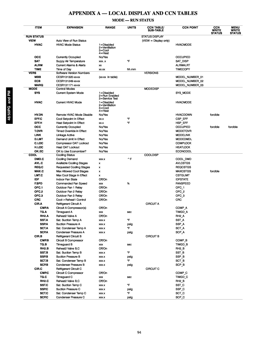
APPENDIX A — LOCAL DISPLAY AND CCN TABLES
MODE — RUN STATUS
ITEM | EXPANSION | RANGE | UNITS | CCN TABLE/ | CCN POINT | CCN | MENU |
|
|
|
| SUBTABLE |
| WRITE | WRITE |
|
|
|
|
|
| STATUS | STATUS |
RUN STATUS |
|
|
| STATUS DISPLAY |
|
|
|
VIEW | Auto View of Run Status |
|
| (VIEW = Display only) |
|
|
|
HVAC | HVAC Mode Status | 1=Disabled |
|
| HVACMODE |
|
|
|
| 2=Ventilation |
|
|
|
|
|
|
| 3=Cool |
|
|
|
|
|
|
| 4=Heat |
|
|
|
|
|
OCC | Currently Occupied | No/Yes |
|
| OCCUPIED |
|
|
SAT | Suppy Air Temperature | xxx..x | °F |
| SAT_DISP |
|
|
ALRM | Current Alarms & Alerts | xx |
|
| ALRMALRT |
|
|
TIME | Time of Day | xx.xx | hh.mm |
| TIMECOPY |
|
|
VERS | Software Version Numbers |
|
| VERSIONS |
|
|
|
MBB | CESR131320xxxx | (xxxx in table) |
|
| MODEL_NUMBER_01 |
|
|
ECB | CESR131249xxxx |
|
|
| MODEL_NUMBER_02 |
|
|
MARQ | CESR131171xxxx |
|
|
| MODEL_NUMBER_03 |
|
|
MODE | Control Modes |
|
| MODEDISP |
|
|
|
SYS | Current System Mode | 1=Disabled |
|
| SYS_MODE |
|
|
|
| 2=Run Enabled |
|
|
|
|
|
|
| 3=Service Test |
|
|
|
|
|
HVAC | Current HVAC Mode | 1=Disabled |
|
| HVACMODE |
|
|
|
| 2=Ventilation |
|
|
|
|
|
|
| 3=Cool |
|
|
|
|
|
|
| 4=Heat |
|
|
|
|
|
HV.DN | Remote HVAC Mode Disable | No/Yes |
|
| HVACDOWN | forcible |
|
EFF.C | Cool Setpoint In Effect | xx.x | °F |
| CSP_EFF |
|
|
EFF.H | Heat Setpoint In Effect | xx.x | °F |
| HSP_EFF |
|
|
OCC | Currently Occupied | No/Yes |
|
| OCCUPIED | forcible | forcible |
T.OVR | Timed Override in Effect | No/Yes |
|
| MODETOVR |
|
|
LINK | Linkage Active | No/Yes |
|
| MODELINK |
|
|
D.LMT | Demand Limit In Effect | No/Yes |
|
| MODEDMDL |
|
|
C.LOC | Compressor OAT Lockout | No/Yes |
|
| COMPLOCK |
|
|
H.LOC | Heat OAT Lockout | No/Yes |
|
| HEATLOCK |
|
|
OK.EC | OK to Use Economizer? | No/Yes |
|
| ECONCOOL |
|
|
COOL | Cooling Status |
|
| COOLDISP |
|
|
|
DMD.C | Cooling Demand | xxx.x | ^F |
| COOL_DMD |
|
|
AVL.C | Available Cooling Stages | x |
|
| AVLCSTGS |
|
|
REQ.C | Requested Cooling Stages | x |
|
| REQCSTGS |
|
|
MAX.C | Max Allowed Cool Stages | x |
|
| MAXCSTGS | forcible |
|
LMT.C | Max Cool Stage In Effect | x |
|
| CSTGLIMT |
|
|
IDF | Indoor Fan State | Off/On |
|
| IDFSTATE |
|
|
F.SPD | Commanded Fan Speed | xxx | % |
| FANSPEED |
|
|
OFC.1 | Outdoor Fan 1 Relay | Off/On |
|
| OFC_1 |
|
|
OFC.2 | Outdoor Fan 2 Relay | Off/On |
|
| OFC_2 |
|
|
OFC.3 | Outdoor Fan 3 Relay | Off/On |
|
| OFC_3 |
|
|
CRC | Cool>Reheat1 Control | Off/On |
|
| CRC |
|
|
CIR.A | Refrigerant Circuit A |
|
| CIRCUIT A |
|
|
|
CMP.A | Circuit A Compressor(s) | Off/On |
|
| COMP_A |
|
|
TG.A | Timeguard A | xxx | sec |
| TIMGD_A |
|
|
RH2.A | Reheat2 Valve A | Off/On |
|
| RH2_A |
|
|
SST.A | Sat. Suction Temp A | xxx.x | °F |
| SST_A |
|
|
SSP.A | Suction Pressure A | xxx.x | psig |
| SSP_A |
|
|
SCT.A | Sat. Condenser Temp A | xxx.x | °F |
| SCT_A |
|
|
SCP.A | Condenser Pressure A | xxx.x | psig |
| SCP_A |
|
|
CIR.B | Refrigerant Circuit B |
|
| CIRCUIT B |
|
|
|
CMP.B | Circuit B Compressor | Off/On |
|
| COMP_B |
|
|
TG.B | Timeguard B | xxx | sec |
| TIMGD_B |
|
|
RH2.B | Reheat2 Valve B,C | Off/On |
|
| RH2_B |
|
|
SST.B | Sat. Suction Temp B | xxx.x | °F |
| SST_B |
|
|
SSP.B | Suction Pressure B | xxx.x | psig |
| SSP_B |
|
|
SCT.B | Sat. Condenser Temp B | xxx.x | °F |
| SCT_B |
|
|
SCP.B | Condenser Pressure B | xxx.x | psig |
| SCP_B |
|
|
CIR.C | Refrigerant Circuit C |
|
| CIRCUIT C |
|
|
|
CMP.C | Circuit C Compressor | Off/On |
|
| COMP_C |
|
|
TG.C | Timeguard C | xxx | sec |
| TIMGD_C |
|
|
RH2.C | Reheat2 Valve B,C | Off/On |
|
| RH2_B |
|
|
SST.C | Sat. Suction Temp C | xxx.x | °F |
| SST_C |
|
|
SSP.C | Suction Pressure C | xxx.x | psig |
| SSP_C |
|
|
SCT.C | Sat. Condenser Temp C | xxx.x | °F |
| SCT_C |
|
|
SCP.C | Condenser Pressure C | xxx.x | psig |
| SCP_C |
|
|
94
