48/50PG and PM
Accessory Navigator Display
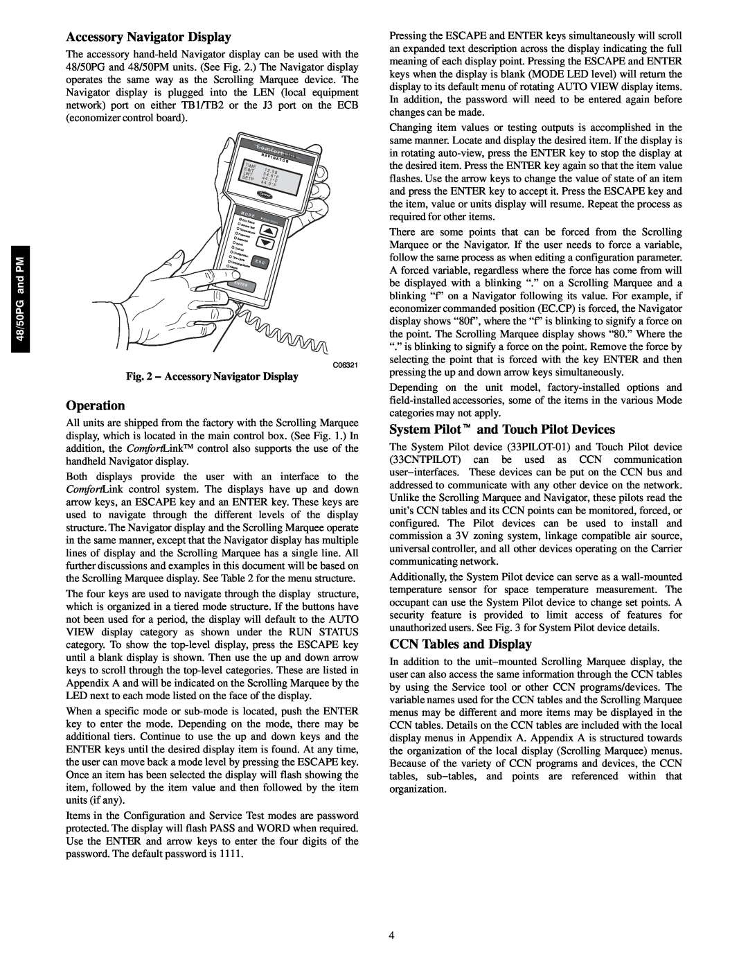
The accessory
|
|
|
|
|
|
| C o | m f | o r | t L |
|
| ||||
|
|
|
|
|
|
| N | i n | k | |||||||
|
|
|
|
|
|
| A V | I | ||||||||
|
|
|
|
|
|
|
| G | A T | |||||||
|
| TIME |
|
|
|
|
|
|
| O R |
| |||||
|
|
| 1 |
|
|
|
|
|
|
|
| |||||
|
| EW | T |
|
| 2 . 5 8 |
|
|
| |||||||
|
| L |
|
|
| 5 |
|
|
| |||||||
|
| WT |
| 4 . | 6 ° | F |
|
|
| |||||||
|
| SE |
|
|
|
| 4 |
|
|
|
|
| ||||
|
| TP |
| 4 . 1 |
|
|
|
|
| |||||||
|
|
|
|
| ° F |
|
|
| ||||||||
|
|
|
|
|
|
| 4 4 | . 0 |
|
|
|
| ||||
|
|
|
|
|
|
| ° F |
|
|
|
| |||||
|
| M O | D E |
|
|
|
|
|
|
|
|
|
|
| ||
|
|
|
| Alarm |
|
|
|
|
|
|
| |||||
|
| Run | Status |
| Sta | tus |
|
|
| |||||||
|
| Service | Test |
|
|
|
|
|
|
|
|
|
|
| ||
| T |
|
|
|
|
|
|
|
|
|
|
|
|
|
| |
| P | empera | tures |
|
|
|
|
|
|
|
|
|
|
| ||
| ress |
|
|
|
|
|
|
|
|
|
|
|
| |||
| Se | ures |
|
|
|
|
|
|
|
|
|
|
|
|
| |
| tpoints |
|
|
|
|
|
|
|
|
|
|
|
|
|
| |
In |
|
|
|
|
|
|
|
|
|
|
|
|
|
| ||
|
|
|
|
|
|
|
|
|
|
|
|
|
|
| ||
| puts |
|
|
|
|
|
|
|
|
|
|
|
|
|
| |
O |
|
|
|
|
|
|
|
|
|
|
|
|
|
|
|
|
| utputs |
|
|
|
|
|
|
|
|
|
|
|
|
|
| |
Con |
|
|
|
|
|
|
|
|
|
|
|
|
|
|
| |
| figuration |
|
|
|
|
|
|
|
|
|
|
|
|
| ||
Time |
|
|
|
|
|
|
|
|
|
|
|
|
|
|
| |
Oper | Clock |
|
|
| E S C |
|
|
|
|
|
|
|
|
| ||
ating M |
|
|
|
|
|
|
|
|
|
|
|
| ||||
Alarms |
| odes |
|
|
|
|
|
|
|
|
|
|
|
|
| |
ENT |
|
|
|
|
|
|
|
|
|
|
|
|
|
| ||
|
| ER |
|
|
|
|
|
|
|
|
|
|
|
|
|
|
C06321
Fig. 2 − Accessory Navigator Display
Operation
All units are shipped from the factory with the Scrolling Marquee display, which is located in the main control box. (See Fig. 1.) In addition, the ComfortLink control also supports the use of the handheld Navigator display.
Both displays provide the user with an interface to the ComfortLink control system. The displays have up and down arrow keys, an ESCAPE key and an ENTER key. These keys are used to navigate through the different levels of the display structure. The Navigator display and the Scrolling Marquee operate in the same manner, except that the Navigator display has multiple lines of display and the Scrolling Marquee has a single line. All further discussions and examples in this document will be based on the Scrolling Marquee display. See Table 2 for the menu structure.
The four keys are used to navigate through the display structure, which is organized in a tiered mode structure. If the buttons have not been used for a period, the display will default to the AUTO VIEW display category as shown under the RUN STATUS category. To show the
When a specific mode or
Items in the Configuration and Service Test modes are password protected. The display will flash PASS and WORD when required. Use the ENTER and arrow keys to enter the four digits of the password. The default password is 1111.
Pressing the ESCAPE and ENTER keys simultaneously will scroll an expanded text description across the display indicating the full meaning of each display point. Pressing the ESCAPE and ENTER keys when the display is blank (MODE LED level) will return the display to its default menu of rotating AUTO VIEW display items. In addition, the password will need to be entered again before changes can be made.
Changing item values or testing outputs is accomplished in the same manner. Locate and display the desired item. If the display is in rotating
There are some points that can be forced from the Scrolling Marquee or the Navigator. If the user needs to force a variable, follow the same process as when editing a configuration parameter. A forced variable, regardless where the force has come from will be displayed with a blinking “.” on a Scrolling Marquee and a blinking “f” on a Navigator following its value. For example, if economizer commanded position (EC.CP) is forced, the Navigator display shows “80f”, where the “f” is blinking to signify a force on the point. The Scrolling Marquee display shows “80.” Where the “.” is blinking to signify a force on the point. Remove the force by selecting the point that is forced with the key ENTER and then pressing the up and down arrow keys simultaneously.
Depending on the unit model,
System Pilott and Touch Pilot Devices
The System Pilot device
Additionally, the System Pilot device can serve as a
CCN Tables and Display
In addition to the unit−mounted Scrolling Marquee display, the user can also access the same information through the CCN tables by using the Service tool or other CCN programs/devices. The variable names used for the CCN tables and the Scrolling Marquee menus may be different and more items may be displayed in the CCN tables. Details on the CCN tables are included with the local display menus in Appendix A. Appendix A is structured towards the organization of the local display (Scrolling Marquee) menus. Because of the variety of CCN programs and devices, the CCN tables, sub−tables, and points are referenced within that organization.
4