48/50PG and PM
Triple Evacuation Method
The triple evacuation method should only be used when vacuum pump is capable of pumping down to 28−in. of mercury and system does not contain any liquid water. Proceed as follows:
1.Pump system down to 28−in. of mercury and allow pump to continue operating for an additional 15 minutes.
2.Close service valves and shut off vacuum pump.
3.Connect a nitrogen cylinder and regulator to system and open until system pressure is 2 psig.
4.Close service valve and allow system to stand for 1 hr. During this time, dry nitrogen will be able to diffuse throughout the system, absorbing moisture.
5.Repeat this procedure. System will then contain minimal amounts of contaminants and water vapor.
Refrigerant Charge
Amount of refrigerant charge is listed on unit nameplate. Refer to Carrier GTAC II; Module 5; Charging, Recovery, Recycling, and Reclamation section for charging methods and procedures. Unit panels must be in place when unit is operating during charging procedure.
Puron
!WARNING
UNIT OPERATION AND SAFETY HAZARD
Failure to follow this warning could cause personal injury, death and/or equipment damage.
Puron (R−410A) refrigerant systems operate at higher pressures than standard R−22 systems. Do not use R−22 service equipment or components on Puron refrigerant equipment. Gauge set, hoses, and recovery system must be designed to handle Puron refrigerant. If unsure about equipment, consult the equipment manufacturer.
NOTE: Do not use recycled refrigerant as it may contain contaminants.
No Charge
Use standard evacuating techniques. After evacuating system, weigh in the specified amount of refrigerant (refer to unit nameplate).
NOTE: System charge for units with
Low Charge Cooling
Using cooling charging chart (see Fig. 58−79), add or remove refrigerant until conditions of the chart are met. An accurate pressure gauge and
To Use the Cooling Charging Chart, Standard Unit
NOTE: All circuits must be running in normal cooling mode. Indoor airflow must be within specified air quantity limits for cooling. (See Appendix D.) All outdoor fans must be on and running at high speed. Use the Cooling Service Test Outdoor Fan Override function to start all outdoor fans.
R410A REFRIGERANT
|
| OUTDOOR FAN MUST BE OPERATING ON HIGH SPEED |
| |||||||
| 160 |
|
|
|
|
|
|
|
|
|
| 140 |
|
|
|
|
|
|
|
|
|
F] |
|
|
|
|
|
|
|
|
|
|
rees | 120 | Add Charge if Above the Curve |
|
|
|
|
| |||
|
|
|
|
|
|
|
|
|
| |
[Deg |
|
|
|
|
|
|
|
|
|
|
re, |
|
|
|
|
|
|
|
|
|
|
eratu | 100 |
|
|
|
|
|
|
|
|
|
|
|
|
|
|
|
|
|
|
| |
Temp |
|
|
|
|
|
|
|
|
|
|
or Coil Leaving | 80 |
|
|
|
|
|
|
|
|
|
60 |
|
|
| Remove Charge if Below the Curve |
|
| ||||
do |
|
|
|
|
|
|
|
|
| |
Out |
|
|
|
|
|
|
|
|
|
|
| 40 |
|
|
|
|
|
|
|
|
|
| 20 |
|
|
|
|
|
|
|
|
|
| 150 | 200 | 250 | 300 | 350 | 400 | 450 | 500 | 550 | 600 |
|
|
|
| Compressor Discharge Pressure, [psig] |
|
|
| |||
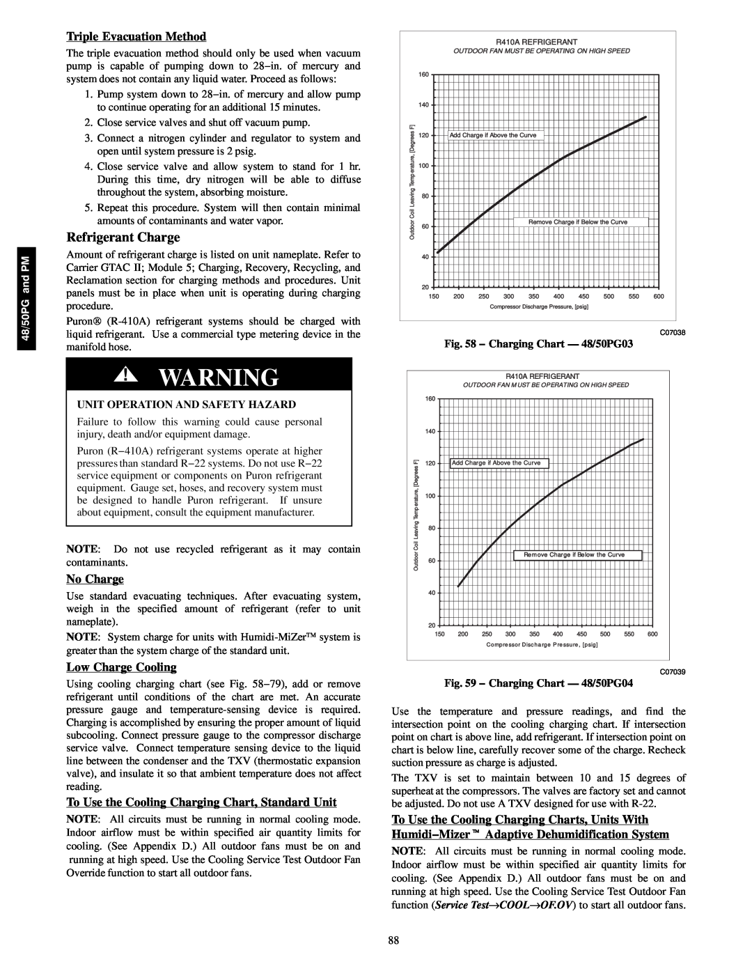
C07038
Fig. 58 − Charging Chart — 48/50PG03
R410A REFRIGERANT
OUTDOOR FAN M UST BE OPERATING ON HIGH SPEED
| 160 |
|
|
|
|
|
|
|
|
|
| 140 |
|
|
|
|
|
|
|
|
|
F] | 120 | Add Charge if Above the Curve |
|
|
|
|
| |||
rees |
|
|
|
|
| |||||
|
|
|
|
|
|
|
|
|
| |
[Deg |
|
|
|
|
|
|
|
|
|
|
re, | 100 |
|
|
|
|
|
|
|
|
|
eratu |
|
|
|
|
|
|
|
|
| |
|
|
|
|
|
|
|
|
|
| |
Temp |
|
|
|
|
|
|
|
|
|
|
or Coil Leaving | 80 |
|
|
|
|
|
|
|
|
|
|
|
|
| Remove Charge if Below the Curve |
| |||||
o | 60 |
|
|
|
|
|
|
|
|
|
Outd |
|
|
|
|
|
|
|
|
| |
|
|
|
|
|
|
|
|
|
| |
| 40 |
|
|
|
|
|
|
|
|
|
| 20 |
|
|
|
|
|
|
|
|
|
| 150 | 200 | 250 | 300 | 350 | 400 | 450 | 500 | 550 | 600 |
|
|
| Compre ssor Disc ha rge P re ssure , [psig] |
|
|
| ||||
C07039
Fig. 59 − Charging Chart — 48/50PG04
Use the temperature and pressure readings, and find the intersection point on the cooling charging chart. If intersection point on chart is above line, add refrigerant. If intersection point on chart is below line, carefully recover some of the charge. Recheck suction pressure as charge is adjusted.
The TXV is set to maintain between 10 and 15 degrees of superheat at the compressors. The valves are factory set and cannot be adjusted. Do not use A TXV designed for use with
To Use the Cooling Charging Charts, Units With Humidi−Mizert Adaptive Dehumidification System
NOTE: All circuits must be running in normal cooling mode. Indoor airflow must be within specified air quantity limits for cooling. (See Appendix D.) All outdoor fans must be on and running at high speed. Use the Cooling Service Test Outdoor Fan function (Service Test→COOL→OF.OV) to start all outdoor fans.
88