E![]()
E ![]()
25.4 ![]() MAX. TYP.
MAX. TYP.
AABB
SECTION
SCALE 2:1
SPARK GAP | D | |
0.181” | ||
[4.6] | SPARK GAP | |
0.120 TO 0.140” | ||
C | ||
| [3.05 TO 3.56] |
| C | D |
|
SECTION | SECTION | SECTION | SECTION |
| SCALE 1:1 | SCALE 1:1 |
|
|
|
| C06269 |
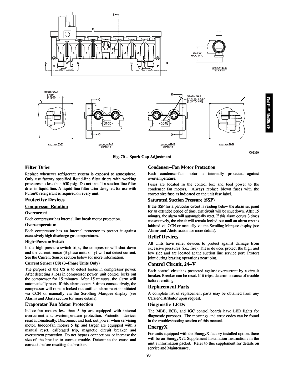
| Fig. 70 − Spark Gap Adjustment |
| |
Filter Drier |
| Condenser−Fan Motor Protection |
|
Replace whenever refrigerant system is exposed to atmosphere. | Each | ||
Only use factory specified | overtemperature. |
| |
pressures no less than 650 psig. Do not install a | Fuses are located in the control box and feed power to the | ||
drier in liquid line. A | condenser fan motors. Always replace | blown fuses with the | |
Puron refrigerant is required on every unit. | correct size fuse as indicated on the unit fuse label. | ||
48/50PG and PM
Protective Devices
Compressor Rotation
Overcurrent
Each compressor has internal line break motor protection.
Overtemperature
Each compressor has an internal protector to protect it against excessively high discharge gas temperatures.
High−Pressure Switch
If the
Current Sensor (CS) (3−Phase Units Only)
The purpose of the CS is to detect losses in compressor power. After detecting a loss in compressor power, unit control locks out the compressor for 15 minutes. After 15 minutes, the alarm will automatically reset. If this alarm occurs 3 times consecutively, the compressor will remain locked out until an alarm reset is initiated via CCN or manually via the Scrolling Marquee display (see Alarms and Alerts section for more details).
Saturated Suction Pressure (SSP)
If the SSP for a particular circuit is reading below the alarm set point for an extended period of time, that circuit will be shut down. After 15 minutes, the alarm will automatically reset. If this alarm occurs 3 times consecutively, the circuit will remain locked out until an alarm reset is initiated via CCN or manually via the Scrolling Marquee display (see Alarms and Alerts section for more details).
Relief Devices
All units have relief devices to protect against damage from excessive pressures (i.e., fire). These devices protect the high and low side and are located at the suction line service port. Protect joint during brazing operations near joint.
Control Circuit, 24−V
Each control circuit is protected against overcurrent by a circuit breaker. Breaker can be reset. If it trips, determine cause of trouble before resetting.
Replacement Parts
A complete list of replacement parts may be obtained from any Carrier distributor upon request.
Evaporator Fan Motor Protection
Diagnostic LEDs
The MBB, ECB, and IGC control boards have LED lights for diagnostic purposes. The meanings and error codes can be found in the troubleshooting section of this manual.
EnergyX
For units equipped with the EnergyX factory installed option, there will be an EnergyXv2 Supplement Installation Instructions in the unit’s information packet. Refer to this supplement for details on service and Maintenance.
93
