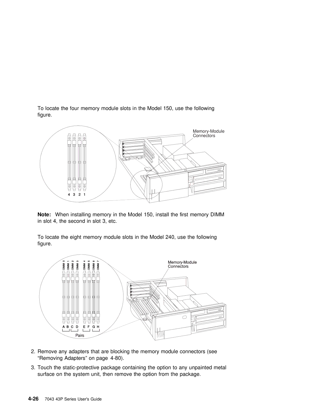
To locate the four memory module slots in the Model 150, use the follow figure.
Memory-Module
Connectors
| 4 | 3 | 2 | 1 |
|
|
Note: | When | installing memory | in the | Model 150, install the first memory DI | ||
in | slot 4, |
| the second in | slot 3, | etc. | |
To locate the eight memory module slots in the Model 240, use the foll figure.
2.Remove any adapters that are blocking the memory module connectors (se “Removing Adapters” on page
3.Touch the
