Installation User’s Guide
Page
Contents
Configuring 802.11g Radio Inbound Filters
AT-WA7500 and AT-WA7501 Installation and User’s Guide
Appendix C
Preface
Document Conventions
Where to Find Web-based Guides
Contacting Allied Telesyn
Management Software Updates
Chapter
Getting Started
Getting Started
AT-WA7500 and AT-WA7501 Installation and User’s Guide
Access Point Architecture
Ttls
Feature AT-WA7500 AT-WA7501
Https
What’s New for Software Releases 2.3?
Icon
Understanding the LEDs
Description
AT-WA7500 LEDs
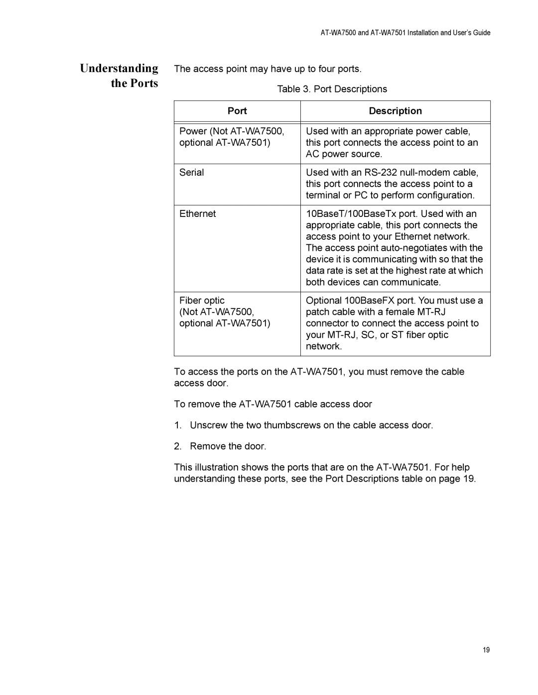
Port Description
Understanding the Ports
10BaseT/100BaseTx Ethernet port Serial port
Using One Access Point in a Simple Wireless Network
How the Access Point Fits in Your Network
Access Point Environment
Access Point
Example Configuring an 802.11g Access Point
Screen
Multiple Access Points with Roaming End Devices
Using Multiple Access Points Roaming Wireless End Devices
11g Access Point with Roaming End Devices
Radio Root
Using an Access Point as a WAP
Screen Parameter
Radio
Access Point as a WAP
AT-WA7500 and AT-WA7501 Installation and User’s Guide
11g WAP with No Roaming End Devices
WAP 802.11b
Example Configuring an 802.11a WAP With Roaming End Devices
Screen Parameter 802.11g Radio-2
Screen Parameter Access Point WAP 802.11a
Using Access Points to Create a Point-to-Point Bridge
With access points that are acting as point-to-point bridges
Getting Started
AT-WA7500 and AT-WA7501 Installation and User’s Guide
11g Bridge
Example Configuring an 802.11g Point-to-Point Bridge
Bridge Secondary Screen Parameter Primary LAN
Bridge
Example Configuring an 802.11a Point-to-Multipoint Bridge
Using Dual Radio Access Points for Redundancy
Using the ATI AT-WA7500 Configuration Wizard
Configuring the Access Point Setting the IP Address
AT-WA7500 and AT-WA7501 Installation and User’s Guide
Using a Communications Program
AT-WA7500 and AT-WA7501 Installation and User’s Guide
Using a Web Browser Interface
AT-WA7500 and AT-WA7501 Installation and User’s Guide
Using a Telnet Session
AT-WA7500 and AT-WA7501 Installation and User’s Guide
Configuration File Description
Saving Configuration Changes
This screen appears
Browser Interface
Using a Telnet Session
Installing the Access Points
Microwave Ovens Cordless Telephones
Installation Guidelines
Other Access Points
Connecting the AT-WA7501 to Your Wired LAN
Installing the AT-WA7501
Connecting the AT-WA7501 to Power
Connecting the AT-WA7500 to Your Wired LAN and Power
Installing the AT-WA7500
Using Purchasing Required Patch Cord Adapter
Connecting to Your Fiber Optic Network
Connecting to an SC Network
Connecting to an MT-RJ Network
Connecting to an ST Network
Female MT-RJ connector ST connector ST adapter
Connecting Power Over Ethernet
External Antenna Placement Guidelines
Positioning Antennas for Antenna Diversity
Positioning Antennas for Dual Radio Access Points
Location Recommended Antenna Separation
About Antenna Diversity for 802.11g Radios
Stacked Antenna Positioning for Dual Radio Access Points
About Antenna Diversity for 802.11a Radios
About Antenna Diversity for 802.11b Radios
Configuring the Ethernet Network
Configuring the TCP/IP Settings
Parameter Explanation
ABC.UVW.COM
Configuring Access Point as a Dhcp Client
ABC.XYZ.COM
Configuring the Ethernet Network
Parameter Explanation
Use Any Available Dhcp Server Access points
Configuring Access Point as a Dhcp Server
Only Use Access Point Dhcp Server Access
Parameter Explanation
Parameter Explanation
Parameter Explanation
Supported Dhcp Server Options
About Network Address Translation NAT
Unsupported Dhcp Server Options
Configuring Access Point to Send ARP Requests
Configuring Other Ethernet or Fiber Optic Settings
Ethernet Parameter Descriptions
Configuring Ethernet Address
Using Ethernet Frame Type Filters
Configuring Ethernet Filters
AT-WA7500 and AT-WA7501 Installation and User’s Guide
Frame Type Explanation
Using Predefined Subtype Filters Customizing Subtype Filters
SubType Value
Example
Dhcp
Configuring Advanced Filters
Setting Filter Values
Filter Parameter Value Explanation
Setting Filter Expressions
Parameter Explanation
Example
Value ID Description
Parameter Value Explanation
Check for a DIX IP frame
Parameter Value Explanation
Parameter Value Explanation
Parameter Value Explanation
Configuring the Radios
About the Radios
Access Radio Supported Dual Point 802.11g
802.11a Independent
Configuring the 802.11g Radio
Parameter Explanation
Enter a unique Ssid for each enabled service
France Japan Israel
Channel
Configuring 802.11g Radio Advanced Parameters
Parameter Description
104
105
106
Configuring 802.11g Radio Inbound Filters
WTP
Applying Hot Settings
109
Configuring the 802.11b Radio
11b Radio Parameter Descriptions
Configuring 802.11b Radio Advanced Parameters
113
‘ANY’
Configuring 802.11b Radio Inbound Filters
SVP
Supported Voice Supported Voice and Data
Configuring a SpectraLink Network
Number
Number of Phones
118
Configuring the 802.11a Radio
120
121
Enter a unique Ssid for each service set. You
Worldwide Frequencies for the 802.11a Radio
Configuring 802.11a Radio Advanced Parameters
125
Configuring 802.11a Radio Inbound Filters
127
128
Configuring the Spanning Tree
About the Access Point Spanning Tree
About Primary LAN Root Access Point
About Secondary LANs Designated Bridges
Wireless Secondary LANs Remote IP Subnets
133
About Ethernet Bridging/Data Link Tunneling
About Routable Non Network Protocols
Configuring the Spanning Tree Parameters
Vlan
138
139
About IP Tunnels
AP4
Creating IP Tunnels
ˆ DIX ARP ˆ Icmp
Using One IP Multicast Address for Multiple IP Tunnels
Outbound Frames
How Frames Are Forwarded Through IP Tunnels
Inbound Frames
Frame Types That Are Never Forwarded
Configuring IP Tunnels
Iapp
Configuring the IP Address List
Using IP Tunnel Frame Type Filters
Configuring IP Tunnel Filters
151
152
Customizing Subtype Filters
Using Predefined Subtype Filters
154
155
Filter Examples
Example
158
159
Comparing IP Tunnels to Mobile IP
Issue IP Tunneling Mobile IP
Igmp
161
Configuring Global Flooding
Configuring Global Parameters
163
164
Configuring Global RF Parameters
166
167
168
Configuring Security
Understanding Security
171
172
173
Enabling Access Methods
Controlling Access to Access Point Menus
ˆ Tftp
175
176
Configuring the Access Point to Use a Password Server
Changing the Default Login
179
Password Parameter Descriptions
Creating a Secure Spanning Tree
182
183
ACL
Using an Access Control List
185
186
Configuring VLANs
188
Configuring WEP 64/128/152 Security
190
191
Implementing an 802.1x Security Solution
Configuring the Access Point as an Authenticator
194
195
When the Access Point Is the Supplicant
Enabling Secure Communications Between Access Points
When the Access Point Is the Authenticator
Configuring Spanning Tree Security
198
Configuring Wi Fi Protected Access WPA Security
200
201
Configuring WPA PSK Security
Configuring WPA 802.1x Security
Configuring the Embedded Authentication Server EAS
Type of Radius Server Maximum Authentications
About the Embedded Authentication Server EAS
Server
About Certificates
Viewing the Certificates Installed on an Access Point
Installing Uninstalling Certificates
209
Configuring the EAS
211
Configuring the Database
213
MAC
Type Field Description User Name Password
Radius
ACL
Peap
Using the Rejected List
TLS
NAS IP
Adding Entries to the Database
Column Description
TTLS/MSCHAP, TTLS/MSCHAP-V2, PEAP/MSCHAP
Clearing the Rejected List
Exporting Importing Databases
218
219
Managing, Troubleshooting, and Upgrading Access Points
Using Wavelink Avalanche Client Management System
Managing the Access Points
Component Description
Configuring Your Access Points to Use Avalanche
223
Managing Your Access Points Using Avalanche
Important Information When Using Avalanche
Using Simple Network Management Protocol Snmp
227
Viewing AP Connections
Maintaining the Access Points
Display Field Description
230
Viewing AP Neighbors
Displays the Ssid advertised in the beacon. This
233
Viewing Port Statistics
Viewing Dhcp Status
Viewing the Events Log
Viewing About This Access Point Screen
Using the LEDs to Locate Access Points
Restoring the Access Point to the Default Configuration
Using Configuration Error Messages
Troubleshooting the Access Points
Configuration Error Message Additional Information
242
243
244
Troubleshooting With the LEDs
Problem/Question Possible Solution/Answer
General Troubleshooting
247
248
249
250
Using LEDs
Troubleshooting the Radios
Using a Communications Program or a Telnet Session
Error Message Explanation
Using Radio MAC Ping 802.11g and 802.11b Radios
253
Using Icmp Echo
Viewing the Security Events Log
Troubleshooting Security
256
Exporting the Security Events Log
General Security Troubleshooting
Recovering a Failed Access Point
Using a Windows NT4/2000/XP PC
Arp -dIPaddress
Upgrading the Access Points
Troubleshooting the Upgrade
Additional Access Point Features
Understanding the Access Point Segments
Understanding Transparent Files
Using AP Monitor Commands
Using the AP Monitor
Entering the AP Monitor
267
Using Content Addressable Memory CAM Mode Commands
Using Test Mode Commands
Using Service Mode Commands
Syntax FB bootsegment datasegment
FB IB ID
Fdel
FFR
275
Entering Command Console Mode
Using Command Console Mode
Using the Commands
To delete the file FILE.DAT from the memory card, enter
Script
Using Tftp Commands
Tftp GET
Tftp PUT
Tftp Server LOG
Tftp Server Stop
Sdvars set serveripaddress
Using sdvars Commands
Sdvars set scriptfilename
Sdvars set checkpoint
Sdvars set starttime
Sdvars set setactivepointers
Sdvars set terminate
Sdvars set nextpoweruptime
Sample script file for upgrading an access point
New Sample Script for Upgrading an Access Point
Creating Script Files
289
Legacy Sample Script for Upgrading Any Access Point
Copying Files To and From the Access Point
EAS Radius Database File
Importing or Exporting an
Transferring Files Using Your Web Browser
Viewing Copying Files Using Your Web Browser
Transferring Files to and from a Tftp Server
Starting or Stopping the Tftp Server
Automatically Upgrading Software
297
Appendix a
Specifications
CSMA/CD
AT-7500 Access Point
MT-RJ
AT-7501 Access Point
301
DQPSK, Dbpsk
Radio Specifications
Ieee 802.11g
Ieee 802.11b
Ieee 802.11a
304
Appendix B
Default Settings
Parameter Range Default Your Site? Name
TCP/IP Settings Menu Defaults
307
Dhcp Server Setup Menu Defaults
Parameter Name Range Default Your Site?
Ieee 802.11g Radio Menu Defaults
310
Ieee 802.11b Radio Menu Defaults
Allow Check/Clear SpectraLink Voice Protocol
Ieee 802.11a Radio Menu Defaults
314
Spanning Tree Settings Menu Defaults
Global Flooding Menu Defaults
RFC1042/DIX
Global RF Parameters Menu Defaults
Through Two sets Hexadecimal Pairs Through FF
Telnet Gateway Configuration Menu Defaults
Ethernet Configuration Menu Defaults
EQ, NE, GT, LE
Ethernet Advanced Filters Menu Defaults
Tunnels Filter Menu Defaults
IP Tunnels Menu Defaults
NNL
SNAP-IP-TCP
DIX-IP-TCP
Snap -IP-UDP
Instant On Menu Defaults
Network Management Menu Defaults
Passwords Menu Defaults
Security Menu Defaults
WPA/PSK
Ieee 802.11 g, b Or a Radio Security Menu Defaults
Range Default Your Site? Name
ACL Radius
WEP, Tkip
Ascii
Acsii
Tkip
SWAP/TLS Ttls
Radius Server List Menu Defaults Spanning Tree Security Menu
Embedded Authentication Server Menu Defaults
Broadcast
ARP Address Resolution Protocol cache
Appendix C
Bfsk Binary Frequency Shift Key
Directional antenna
Dhcp Dynamic Host Configuration Protocol
EAP Extensible Authentication Protocol
Designated bridge
Hello period
Iapp Inter Access Point Protocol
Ethernet bridging
Flooding
IP tunneling
Igmp Internet Group Management Protocol
IP router
IP subnet
Omni antenna
Multicast address
NAT Network Address Translation
Non-bridging secondary LAN
Primary bridging
Power bridge
Root access point
Point-to-point bridge
Secondary bridging
Service set
Root port
Root IP subnet
Telnet Gateway
Swap Secure Wireless Authentication Protocol
Spanning tree
Splitter
Wireless hop
WAP Wireless Access Point
WEP Wired Equivalent Privacy encryption
Wireless bridge
WPA Wi-Fi Protected Access