Release 1.2 555-233-116 Issue 4 October
Copyright 2002, Avaya Inc All Rights Reserved
Electromagnetic Compatibility EMC Standards
SOC/REN
European Union Declarations of Conformity
Page
Contents
Extenders for 2-wire DCP endpoints
External modems
Terminal server installation 121
Definity Inads
Malicious call trace 189 Music-on-hold 191
Multimedia communications Products MMCX, MMCH, ESM 207
Connector and cable pinout charts 231 Index 243
Overview
About this book
On next
Internet Telephony Server-Enterprise Hardware Installation
Conventions used in this book
Admonishments
Systems and circuit packs
Antistatic protection
Remove/install circuit packs
Physical dimensions
Standards compliance
Security
Click Product Documentation
How to get this book on the Web
Laser product
Trademarks
Tell us what you think
How to get help
About this book Issue 4 October 555-233-116
909A/B universal coupler
Typical 909A/B universal coupler
BSY2/BY2
Typical modular jack pinout
Auxiliary power supplies
Applications that require auxiliary power
Local auxiliary power supply
Required safety precautions
Sources of auxiliary local power
Circuit protection
1145B power supply
Mountings
Installing the wall mounting
1146 mounting arrangement
Installing and wiring the battery
Installing the 1146 power distribution unit
Installing the expanded power distribution unit
Expanded power distribution unit
Power-supply LEDs LED Color Meaning
Powering up and testing AC and DC power
Typical wiring to a terminal
Wire the 1146 power distribution unit
Storing the batteries in inactive units
1151A and 1151A2 power supplies
Repairing short circuits and resetting red LEDs
Replacing the batteries
Typical 1151A power supply front
Standards compliance
Desk mounting
Wall mounting
Wire DCP endpoints
Extenders for 2-wire DCP endpoints
Typical connections to a 2-wire DCP workstation
Typical DCP extender connections
DCP extender, stand alone
DCP extender, rack mount
Data modules and asynchronous data Units
Understanding RS-232 communications
Typical connections to a data module
Installation procedure
Set hardware options
Setting 7400A data module hardware options
Obtain required equipment
Data module mode selector
Data module
Setting 7400B data module hardware options
Down
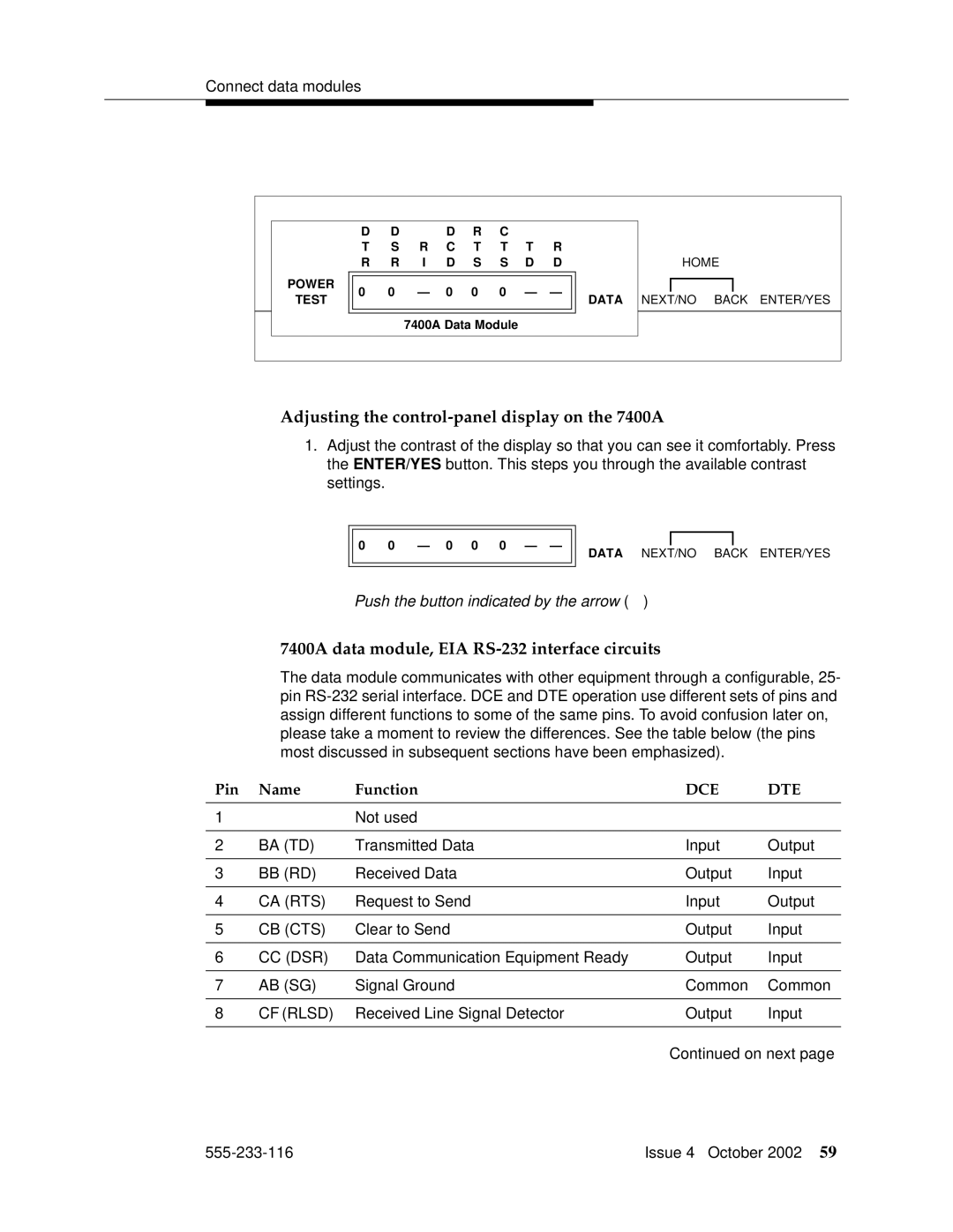
Connect data modules
Connecting a single data module
Z77A data mounting
Connecting multiple data modules to the system
Configuring the 7400A data module
Powering up the 7400A
Using the 7400A menu system
7400A data module, EIA RS-232 interface circuits
Adjusting the control-panel display on the 7400A
CI2
Data Signal Rate Select 2 DCE Source Input
Setting interface options on 7400A DCE
Select an option NEXT/NO or ENTER/YES
Setting speed options on 7400A DCE
Setting the automatic-answer feature on 7400A DCE
Configuring the RS-232 interface on 7400A DCE
Setting the break-disconnect option on 7400A DCE
Enabling remote loopback testing on 7400A DCE
Setting parity on 7400A DCE
Enabling remote loopback on 7400A DCE
Configuring the ring indicator on 7400A DCE
Exiting menus and saving changes on 7400A DCE
Enabling test mode on 7400A DCE
Configuring the 7400A for modem pooling DTE applications
Checking Definity administration on 7400A DCE
Setting speed options on 7400A DTE
SET AT CONTROL?
Configuring the RS-232 interface on 7400A DTE
CI2 CH2
? ?
Restoring factory defaults on 7400A DTE
Test RESET?
Local LOOP/ST?
Displaying the current configuration on the 7400B
Configuring the 7400B Data Module
Installing required configuration equipment for the 7400B
Selecting command mode on the 7400B
At &c1 &d2 q1 s0=1 &w0 &y0 where
Configuring the 7400B for remote administration
Restoring factory defaults for the 7400B
Setting the data speed for the 7400C
Exiting command mode on the 7400B
Configuring the 7400C HSL high- speed link data module
To change the existing speed, press NEXT/NO
Configuring the 7400C for a dedicated private line
Setting other data options for the 7400C
Recommended settings for typical configurations
Configuring the 7400D data module
Accessing the menus of the 7400D
Setting speed options for the 7400D
Push the button indicated by the arrow
Setting the automatic-answer feature on the 7400D
Configuring the RS-232 interface of the 7400D
CH = correctSetting?
DCD = correctValue ?
DTR = correctValue MSEC?
SET LL DETECT?
Sigls Disc = ON?
Selecting 8400B options
Configuring the 8400B Plus data module
Installing required configuration equipment for the 8400B
+ 2 + 16 =
Configuring the ExpressRoute 1000 data module
128
Typical ExpressRoute 1000 data module connections
Administer the data modules
Add data-module next
Screen 1. Typical system-configuration listing
Screen 2. Typical data-module form
Z3A2 ADU
Asynchronous data units ADU
External modems
Hardware required when configuring modems
Paradyne Comsphere
Configuring the 3715 for CMS
Configuring the 3715 for modem pooling
AT&F&D2&S4\D3S2=128x7V2S7=60S85=1
Configuring the 3810 Plus and 3811 Plus modems
ATY0S10=100S78=2M0E0\N1&W The modem is now configured
Paradyne Comsphere 3810 Plus
Understanding the modem controls and displays
Configuring the 3910 for CMS
Press F1 to select Choose Function
Creating an editable configuration set
Copying factory default settings
Loading the copied default settings
Configuring the RS-232 DTR and DSR ready signals
Configuring the DTE interface
Configuring basic, RS-232 handshaking
Finishing configuration of the DTE interface
Configuring RS-232 RTS and CTS send signals
Configuring various control features
Skipping to the result-code options
Configuring the DTE dialer
Opening the DTE Dialer menus
Exiting the DTE Dialer menu
Configuring the data line
Setting the line rate
Disabling result codes
Dial Tx Level Permissv -9 menu heading appears
Saving the new configuration
V22b Guard Tone Disable menu heading appears
Exiting the dial line menu
Checking the status of the Comsphere 3910 modem
Configuring U.S. Robotics modems
Robotics modems
Multi-Tech MT5634ZBA-USB
Administration
Configuring the MT5634ZBA-USB modem
Accessing the administration form
Set the Auto-Answer Ring Number field to S0=10
Setting data-transmission parameters
Setting dialing parameters
Exiting the form and saving the changes
Setting additional, modem-specific parameters
Task list
Connecting printers using TCP/IP
Printers
System printer
Administering adjunct parameters
Testing the switch-to-adjunct link
PMS journal and PMS log printers
Setting up the PC
Setting up an RSP configuration
Setting up the switch
Downloading RSP
Installing RSP
Administering RSP
How the DLG application works
What is the Definity LAN gateway?
Definity LAN gateway system7
Mapd DLG
How is the DLG application is packaged
Co-resident DLG
Switch-based connectivity co-resident DLG
Definity LAN gateway system Issue 4 October 555-233-116
Switch-to-adjunct LAN connectivity through a terminal server
Terminal server installation
Distance limits
Installing and administering the terminal server
Making the connections
Cabling diagram
Administering the IOLAN+
Navigating the IOLAN+ terminal server
Setting up HyperTerminal on the computer
Administering the IOLAN+ the first time
Administration Menu
Select Admin mode Password and press Enter
Reboot Reboot Server
Rebooting the IOLAN+
Administering an IOLAN+ port
Administering the gateway
Name port number or other descriptive name
Testing
Type change node-names ip and press Return
Administering IP node names
Potential failure scenarios and repair actions
Node Names
Administering IP services
Session Layer
Terminal server installation Issue 4 October 555-233-116
With a smart jack
Installing a loopback jack
DS1/T1 CPE loopback jack9
Without a smart jack
Testing the DS1 span from the Icsu to the loopback jack
Administering the loopback jack
Loopback testing with a smart jack
Busying out the DS1 circuit pack
Administering the DS1 for the test
Testing the integrity of the loopback circuit
Checking the integrity of local equipment
Clearing the results of previous tests
Testing the integrity of data sent over the loop
Jack field is Pattern 3-in-24
Running the data test
Value of the Test cpe-loopback
Condition Solution
ConditionSolution
Restoring DS1 administration
Releasing the DS1 circuit pack
Page
Network interface at smart jack for a 120A2 or later Icsu
Prdfcs7a KLC
555-233-116 Issue 4 October 2002
Prdfcs4a KLC
555-233-116 Issue 4 October 2002
Prdfcs5a KLC
Network interface at dumb block for a 120A2 or later Icsu
Testing a loopback jack without a smart jack
Prdfcs8a KLC
555-233-116 Issue 4 October 2002
Prdfcs6a KLC
Page
Configurations using fiber multiplexers
Isdn converters and adapters10
PRI-to-DASS and PRI-to-DPNSS converters
Converters for single-carrier cabinets
Typical PRI to BRI converter cabling
PRI-to-BRI converter
Converters for multi-carrier cabinets
Converters for multi-carrier cabinets
Isdn converters and adapters Issue 4 October 555-233-116
Set clock options
Stratum 3 clock
ST3 clock board option switch settings Switch Status/Results
Cabling the Stratum 3 clock
Typical connections to Stratum 3 clock
BL-W/2
Stratum 3 clock wiring installation procedure
BL/1
Bclkrtn ALRM5B Bclklst ALRM5A Bpwrrtn
RREF1
EXTSYN1R CCA02R
Typical cabling for busy tone disconnect
Busy tone disconnect equipment for Non-U.S. installations12
Page
Connecting CDR equipment
Call detail recording CDR option Settings
Administering CDR parameters
Using other equipment as the CDR output devices
Sources of administration information
Connecting a CDR device
Connecting a CDR device CDR System Parameters screen appears
‘‘Downloading RSP’’ ‘‘Installing RSP’’ ‘‘Administering RSP’’
Downloading RSP
Page
Analog loopback
Definity INADS14
Analog loopback connections
Type add term-ext-group number or next and press Enter
Administration
Partner installation
Type change system-parameters maintenance and press Enter
Check local regulations regarding this connection method
Inads connection with power fail transfer
Inads connection European platform
Standard reliability
High reliability
Inads connection without power fail transfer
European platform connection
Normal connection
Atlas/Spain platform connection
Set incoming line ringing all platforms
Definity ECS administration
Set Partner CO line port all platforms
Set automatic line selection outgoing trunk all platforms
Example of an ART script file
Installation test all installations
Connectivity for Inads on S8700 S8300 media servers
Issue 4 October 555-233-116
Malicious call trace
Malicious call trace15
Page
For MCC1, SCC1, CMC1, and G600 Media Gateways
Music-on-hold
Nonregistered music source
Registered music source
Page
For G700 Media Gateways
For G700 Media Gateways
Music-on-hold Issue 4 October 555-233-116
Background information
Paging and announcement Equipment
IP trunk IP solutions mode
IP configurations
LAN
Multi-site environment
Configuration using the S8700 Media Server with IP connect
S8700 Media Server with IP connect
Loudspeaker paging without paging adapter
Loudspeaker paging with universal coupler
Loudspeaker paging access without universal coupler
Typical Espa radio paging connections
Espa radio paging
External ringing
Queue warning indicator
Loudspeaker paging for G700 Media Gateways
Masi for Mmcx
Multimedia communications Products MMCX, MMCH, ESM18
Modular jack pin assignment
Direction connection
Main distribution frame connection
Nonsignaling configuration
Wideband endpoints
Typical nonsignaling wideband configuration
Signaling configuration
Typical signaling wideband configuration
Connect the endpoints
Multimedia call handling Mmch
Typical multimedia call handling connections
Setup and test the Mmch installation
Administer the system
Administer the endpoints
Administer one number complex
Double click on the PictureTel Live Configure icon
Configuring the PictureTel PCS50 Live 50 and PCS100
Troubleshooting PictureTel
How to place a PictureTel video call
Select restart windows
ProShare configuration
Troubleshooting ProShare
How to place a ProShare video call
Vistium configuration
How to place a Zydacron video call
Zydacron configuration
Place conversion test call
Troubleshooting Zydacron
Expansion services module
Typical multimedia call handling ESM connections
ESM installation
Place test call
Troubleshooting
Status esm Status signaling-group List MMI
Issue 4 October 555-233-116
Property management system PMS
Connecting the property management system PMS
Using data modules
Connecting a terminal and/or journal printer
TCP/IP
Connecting PMS and printers using
PMS, PMS journal, and PMS log printers
Using the downloadable reliable session-layer protocol tool
Downloading RSP
Connector and cable pinout charts
BR-R
Plug
DS1 interface Cable H600-307 50-Pin 15-Pin Color Designation
TXT.1
PXR.7 BR-BK
210 311 211 312 212 313
BR-V
Cenab TXR.1
CP2SCLK TXR.4
Sclk TXT.7
Page
Numerics
Index
Index
121
Index