CHAPTER 3
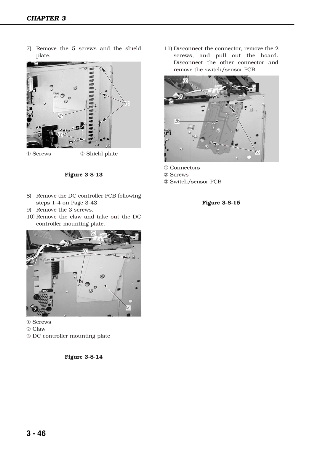
7)Remove the 5 screws and the shield plate.
![]() ➀
➀
➁![]()
➀![]()
➀ Screws | ➁ Shield plate |
Figure
8)Remove the DC controller PCB following steps
9)Remove the 3 screws.
10)Remove the claw and take out the DC controller mounting plate.
➁
➀
➂
➀Screws
➁ Claw
➂ DC controller mounting plate
Figure
11)Disconnect the connector, remove the 2 screws, and pull out the board. Disconnect the other connector and remove the switch/sensor PCB.
➀
➂![]()
![]() ➁
➁
➀Connectors
➁Screws
➂Switch/sensor PCB
Figure
3 - 46
