CHAPTER 3
III.MAIN UNITS
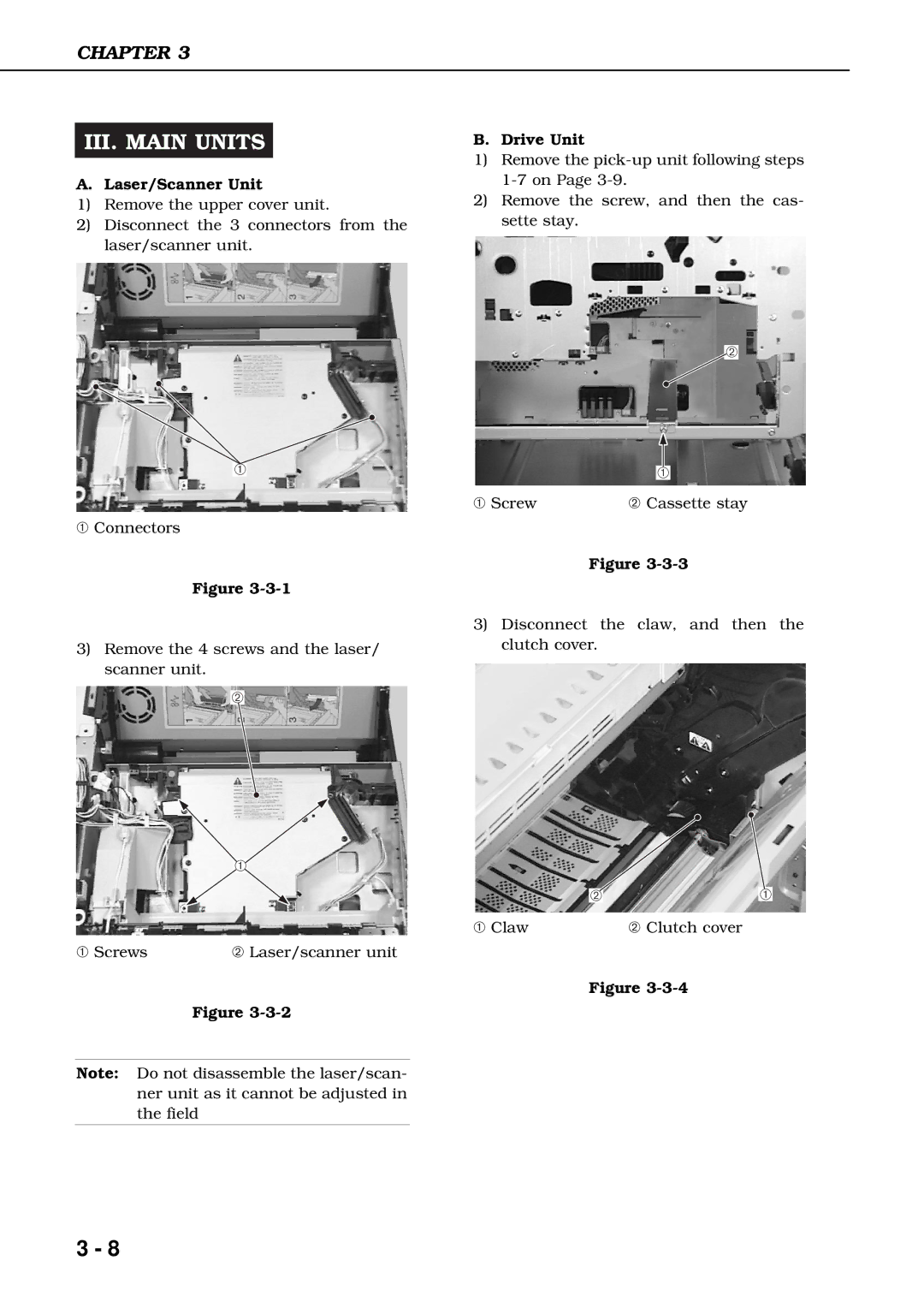
A.Laser/Scanner Unit
1)Remove the upper cover unit.
2)Disconnect the 3 connectors from the laser/scanner unit.
➀
➀Connectors
Figure
3)Remove the 4 screws and the laser/ scanner unit.
➁
➀ |
➀ Screws | ➁ Laser/scanner unit |
Figure
Note: Do not disassemble the laser/scan- ner unit as it cannot be adjusted in the field
B. Drive Unit
1)Remove the
2)Remove the screw, and then the cas- sette stay.
➁
➀
➀ Screw | ➁ Cassette stay |
Figure
3)Disconnect the claw, and then the clutch cover.
➁➀
➀ Claw | ➁ Clutch cover |
Figure
3 - 8