CHAPTER 4
VII. MEASUREMENT AND ADJUSTMENT
A. Mechanical Adjustment
1. Checking the nip width of the lower fixing roller
The fixing unit is not designed to allow adjustment of the pressure (nip width); however, the incorrect nip width can cause fixing problems.
Follow the procedures below to check the nip width:
1)Make an
2)Place the
3)Press the test print switch.
4)Turn OFF the printer when the leading edge of the print emerges at the
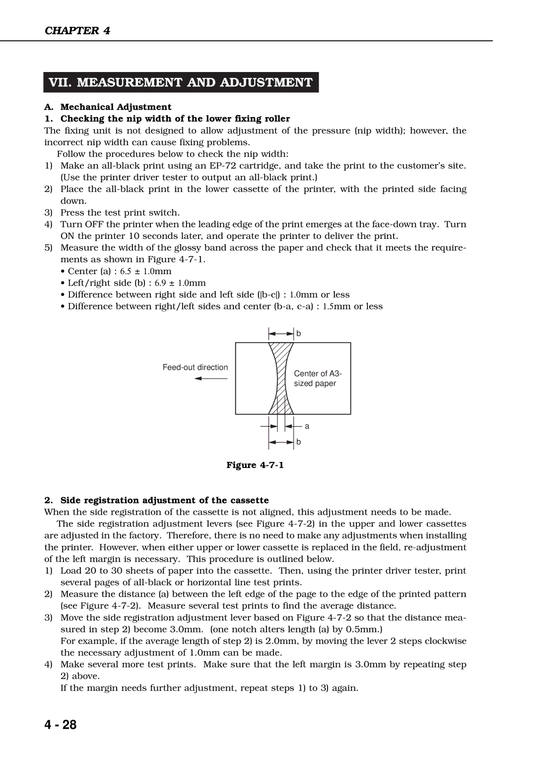
5)Measure the width of the glossy band across the paper and check that it meets the require- ments as shown in Figure
•Center (a) : 6.5 ± 1.0mm
•Left/right side (b) : 6.9 ± 1.0mm
•Difference between right side and left side
•Difference between right/left sides and center
![]()
![]() b
b
Center of A3- sized paper
a
![]()
![]() b
b
Figure
2. Side registration adjustment of the cassette
When the side registration of the cassette is not aligned, this adjustment needs to be made. The side registration adjustment levers (see Figure
are adjusted in the factory. Therefore, there is no need to make any adjustments when installing the printer. However, when either upper or lower cassette is replaced in the field,
1)Load 20 to 30 sheets of paper into the cassette. Then, using the printer driver tester, print several pages of
2)Measure the distance (a) between the left edge of the page to the edge of the printed pattern (see Figure
3)Move the side registration adjustment lever based on Figure
For example, if the average length of step 2) is 2.0mm, by moving the lever 2 steps clockwise the necessary adjustment of 1.0mm can be made.
4)Make several more test prints. Make sure that the left margin is 3.0mm by repeating step 2) above.
If the margin needs further adjustment, repeat steps 1) to 3) again.
4 - 28