CHAPTER 2
B. Fixing Control
1. Fixing temperature control
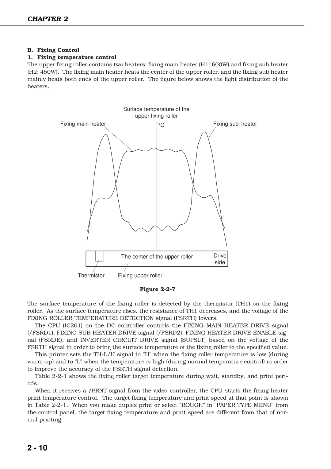
The upper fixing roller contains two heaters: fixing main heater (H1: 600W) and fixing sub heater
(H2: 450W). The fixing main heater heats the center of the upper roller, and the fixing sub heater mainly heats both ends of the upper roller. The figure below shows the light distribution of the heaters.
Surface temperature of the
upper fixing roller
Fixing main heater
°C | Fixing sub heater |
|
| The center of the upper roller | Drive |
|
|
| side |
|
|
|
|
Thermistor | Fixing upper roller |
| |
Figure
The surface temperature of the fixing roller is detected by the thermistor (TH1) on the fixing roller. As the surface temperature rises, the resistance of TH1 decreases, and the voltage of the FIXING ROLLER TEMPERATURE DETECTION signal (FSRTH) lowers.
The CPU (IC201) on the DC controller controls the FIXING MAIN HEATER DRIVE signal (/FSRD1), FIXING SUB HEATER DRIVE signal (/FSRD2), FIXING HEATER DRIVE ENABLE sig- nal (FSRDE), and INVERTER CIRCUIT DRIVE signal (SUPSLT) based on the voltage of the FSRTH signal in order to bring the surface temperature of the fixing roller to the specified value.
This printer sets the
Table
When it receives a /PRNT signal from the video controller, the CPU starts the fixing heater print temperature control. The target fixing temperature and print speed at that point is shown in Table
2 - 10