CHAPTER 2
III.LASER/SCANNER SYSTEM
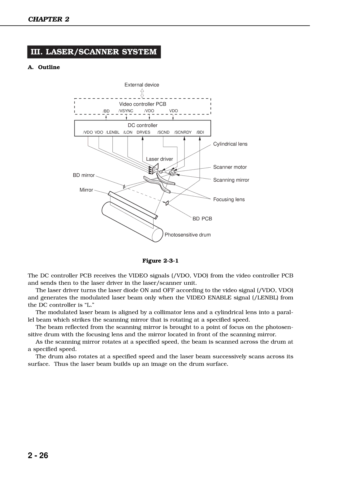
A.Outline
External device
Video controller PCB
/BD /VSYNC /VDO VDO
DC controller
/VDO VDO /LENBL /LON DRVES /SCND /SCNRDY /BDI
Cylindrical lens
Laser driver
Scanner motor
BD mirror
Scanning mirror
Mirror
Focusing lens
BD PCB
Photosensitive drum
Figure
The DC controller PCB receives the VIDEO signals (/VDO, VDO) from the video controller PCB and sends then to the laser driver in the laser/scanner unit.
The laser driver turns the laser diode ON and OFF according to the video signal (/VDO, VDO) and generates the modulated laser beam only when the VIDEO ENABLE signal (/LENBL) from the DC controller is “L.”
The modulated laser beam is aligned by a collimator lens and a cylindrical lens into a paral- lel beam which strikes the scanning mirror that is rotating at a specified speed.
The beam reflected from the scanning mirror is brought to a point of focus on the photosen- sitive drum with the focusing lens and the mirror located in front of the scanning mirror.
As the scanning mirror rotates at a specified speed, the beam is scanned across the drum at a specified speed.
The drum also rotates at a specified speed and the laser beam successively scans across its surface. Thus the laser beam builds up an image on the drum surface.
2 - 26