CHAPTER 2
As shown in Figure
The
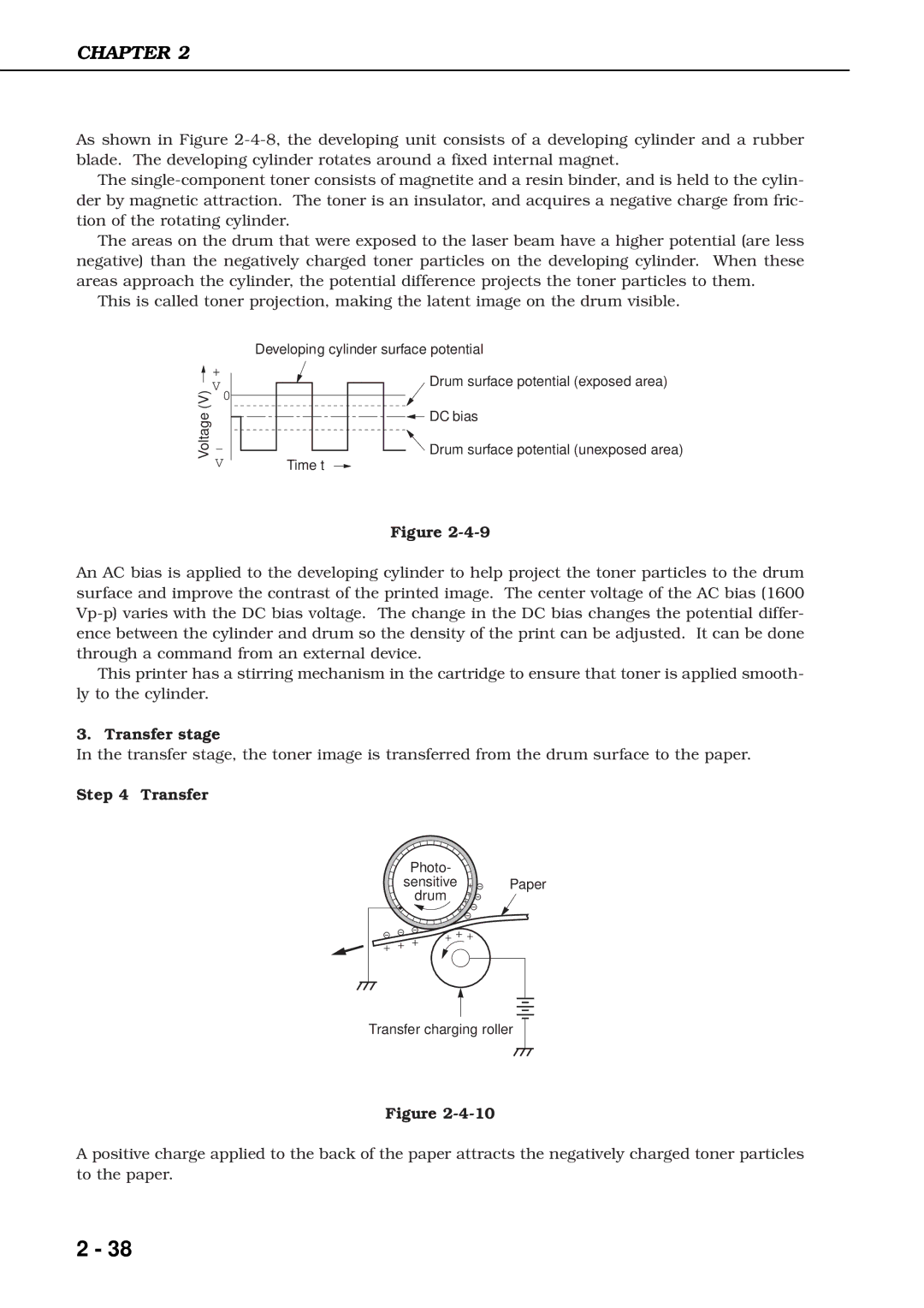
The areas on the drum that were exposed to the laser beam have a higher potential (are less negative) than the negatively charged toner particles on the developing cylinder. When these areas approach the cylinder, the potential difference projects the toner particles to them.
This is called toner projection, making the latent image on the drum visible.
Voltage (V)
+
V
0
-
V
Developing cylinder surface potential
Drum surface potential (exposed area)
DC bias
![]()
![]()
![]() Drum surface potential (unexposed area) Time t
Drum surface potential (unexposed area) Time t ![]()
Figure
An AC bias is applied to the developing cylinder to help project the toner particles to the drum surface and improve the contrast of the printed image. The center voltage of the AC bias (1600
This printer has a stirring mechanism in the cartridge to ensure that toner is applied smooth- ly to the cylinder.
3. Transfer stage
In the transfer stage, the toner image is transferred from the drum surface to the paper.
Step 4 Transfer
Photo-
sensitive ![]() Paper drum
Paper drum ![]()
Transfer charging roller
Figure
A positive charge applied to the back of the paper attracts the negatively charged toner particles to the paper.
2 - 38