CHAPTER 2
|
|
|
|
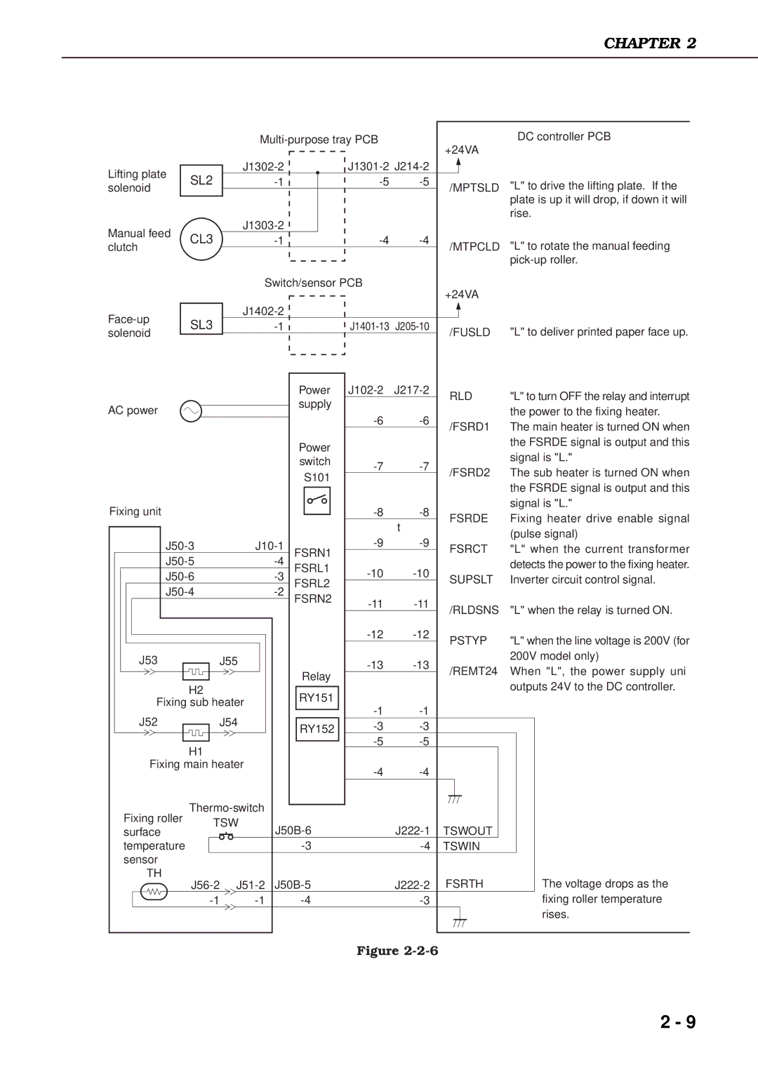
| +24VA | DC controller PCB | |||
|
|
|
|
|
|
|
|
| |
Lifting plate | SL2 |
|
|
|
| ||||
|
|
| "L" to drive the lifting plate. If the | ||||||
solenoid |
|
|
| /MPTSLD | |||||
|
|
|
|
|
|
| |||
|
|
|
|
|
|
|
|
| plate is up it will drop, if down it will |
|
|
|
|
|
|
|
| rise. | |
Manual feed | CL3 |
|
|
|
|
|
| ||
|
|
| "L" to rotate the manual feeding | ||||||
clutch |
|
|
| /MTPCLD | |||||
|
|
|
|
|
|
| |||
|
|
|
|
|
|
|
|
| |
|
|
|
| Switch/sensor PCB |
| +24VA |
| ||
|
|
|
|
|
|
|
|
| |
| SL3 |
|
|
|
|
|
| ||
|
|
|
| "L" to deliver printed paper face up. | |||||
solenoid |
|
|
| /FUSLD | |||||
|
|
|
|
|
|
| |||
|
|
|
|
| Power | RLD | "L" to turn OFF the relay and interrupt | ||
|
|
|
|
| supply |
|
| ||
AC power |
|
|
|
|
|
|
| the power to the fixing heater. | |
|
|
|
|
|
| ||||
|
|
|
|
|
| /FSRD1 | The main heater is turned ON when | ||
|
|
|
|
|
|
|
| ||
|
|
|
|
| Power |
|
|
| the FSRDE signal is output and this |
|
|
|
|
|
|
|
| signal is "L." | |
|
|
|
|
| switch |
| |||
|
|
|
|
| /FSRD2 | The sub heater is turned ON when | |||
|
|
|
|
| S101 | ||||
|
|
|
|
|
|
| |||
|
|
|
|
|
|
|
| the FSRDE signal is output and this | |
|
|
|
|
|
|
|
|
| |
Fixing unit |
|
|
|
|
|
| signal is "L." | ||
|
|
|
|
| FSRDE | Fixing heater drive enable signal | |||
|
|
|
|
|
|
| t | ||
|
|
|
|
|
|
|
| (pulse signal) | |
|
|
|
| ||||||
|
| FSRN1 | FSRCT | "L" when the current transformer | |||||
|
|
|
|
| detects the power to the fixing heater. | ||||
|
| FSRL1 |
| ||||||
|
| SUPSLT | Inverter circuit control signal. | ||||||
|
| FSRL2 | |||||||
|
|
|
|
|
| ||||
|
| FSRN2 | /RLDSNS | "L" when the relay is turned ON. | |||||
|
|
|
|
|
| ||||
|
|
|
|
|
|
|
| ||
|
|
|
|
|
| PSTYP | "L" when the line voltage is 200V (for | ||
|
|
|
|
|
|
|
| ||
J53 |
|
| J55 |
|
| 200V model only) | |||
|
|
| /REMT24 | When "L", the power supply uni | |||||
|
|
|
|
| Relay | ||||
|
|
|
|
|
|
| |||
|
|
|
|
|
|
|
| outputs 24V to the DC controller. | |
|
| H2 |
|
| RY151 |
|
|
| |
|
|
|
|
|
|
|
| ||
Fixing sub heater |
|
|
|
| |||||
|
|
| |||||||
J52 |
|
| J54 |
|
|
| |||
|
| RY152 |
|
| |||||
|
|
|
|
|
|
| |||
|
| H1 |
|
|
|
|
| ||
|
|
|
|
|
|
|
|
| |
Fixing main heater |
|
|
| ||||||
|
|
|
|
|
|
|
| ||
Fixing roller |
|
|
|
|
| ||||
| TSW |
|
| TSWOUT |
| ||||
surface |
|
|
|
|
| ||||
|
|
|
|
| |||||
temperature |
|
|
|
| TSWIN |
| |||
sensor |
|
|
|
|
|
|
|
|
|
TH |
|
| FSRTH | The voltage drops as the | |||||
|
|
| |||||||
|
|
|
| fixing roller temperature | |||||
|
|
|
|
|
|
|
|
| rises. |
|
|
|
|
|
| Figure |
|
| |
2 - 9