CHAPTER 4
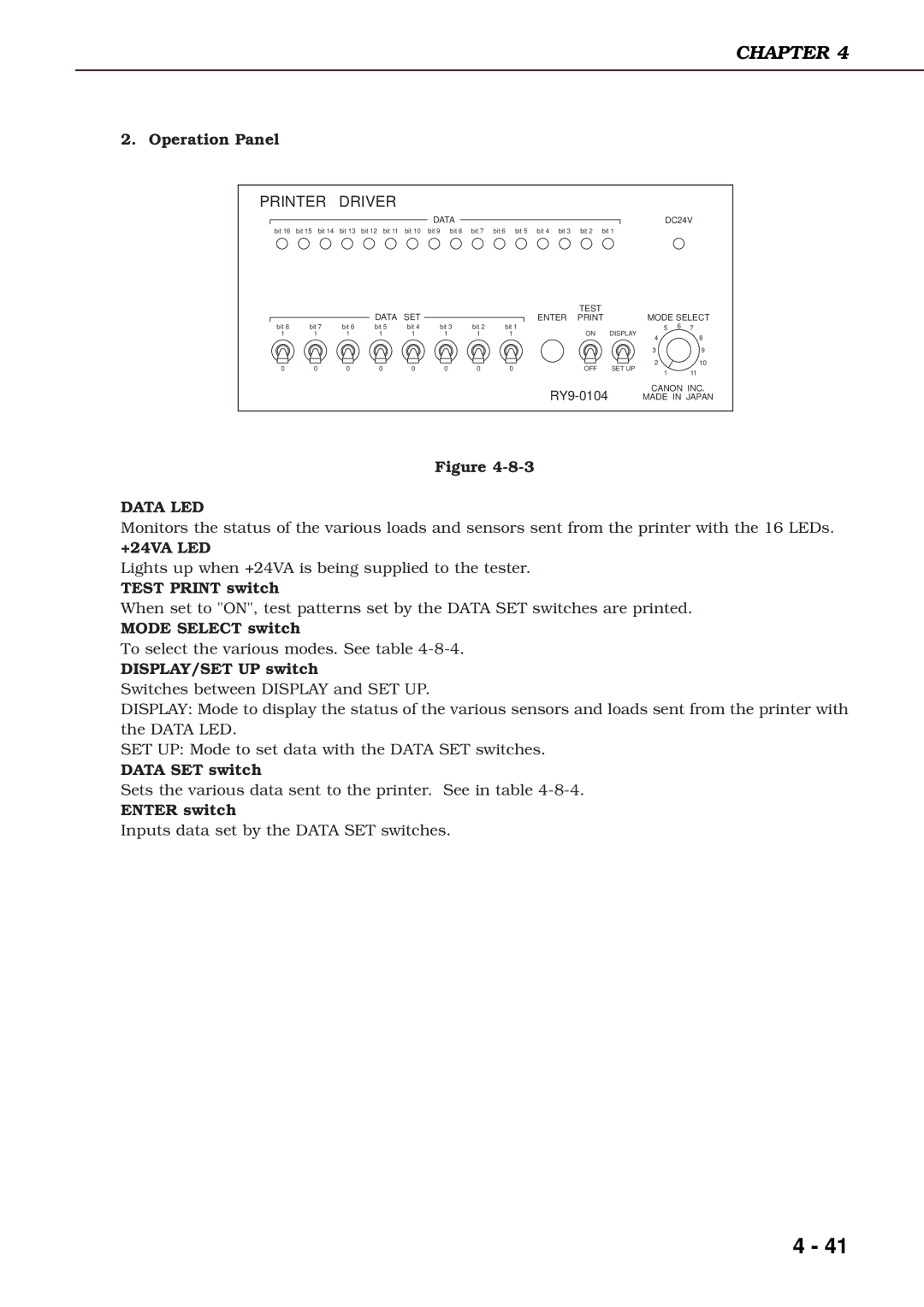
2. Operation Panel
PRINTER DRIVER
DATA
DC24V
bit 16 bit 15 bit 14 bit 13 bit 12 bit 11 bit 10 bit 9 bit 8 bit 7 bit 6 bit 5 bit 4 bit 3 bit 2 bit 1
|
|
| DATA | SET |
bit 8 | bit 7 | bit 6 | bit 5 | bit 4 |
1 | 1 | 1 | 1 | 1 |
0 | 0 | 0 | 0 | 0 |
|
|
| TEST |
|
|
| |
|
| ENTER |
| MODE SELECT | |||
bit 3 | bit 2 | bit 1 | ON | DISPLAY | 5 | 6 7 | |
1 | 1 | 1 | 4 | 8 | |||
|
|
|
|
| |||
|
|
|
|
| 3 | 9 | |
0 | 0 | 0 | OFF | SET UP | 2 | 10 | |
1 | 11 | ||||||
|
|
|
|
| |||
CANON INC. | |
MADE IN JAPAN |
Figure
DATA LED
Monitors the status of the various loads and sensors sent from the printer with the 16 LEDs.
+24VA LED
Lights up when +24VA is being supplied to the tester.
TEST PRINT switch
When set to "ON", test patterns set by the DATA SET switches are printed.
MODE SELECT switch
To select the various modes. See table
DISPLAY/SET UP switch
Switches between DISPLAY and SET UP.
DISPLAY: Mode to display the status of the various sensors and loads sent from the printer with the DATA LED.
SET UP: Mode to set data with the DATA SET switches.
DATA SET switch
Sets the various data sent to the printer. See in table
ENTER switch
Inputs data set by the DATA SET switches.
4 - 41