CHAPTER 2
C. Scanning System
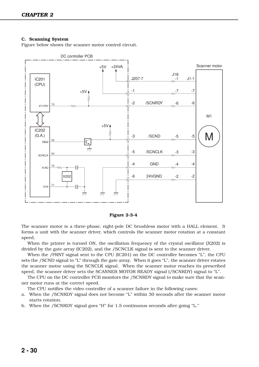
Figure below shows the scanner motor control circuit.
DC controller PCB
| +5V | +24VA |
|
IC201 |
|
| |
(CPU) |
|
|
|
| +5V |
| |
XT1/P07 | 73 | /SCNRDY | |
|
|
| |
| +5V |
|
|
IC202 |
|
|
|
(G.A.) |
| /SCND | |
DB22 | 52 |
|
|
|
|
| |
SCNCLK | 54 | /SCNCLK | |
|
| ||
|
|
| |
X1AO | 70 | GND | |
|
| ||
|
|
| |
| X202 | 24VGND | |
X1AI | 71 |
|
|
|
|
| |
|
| Figure |
|
J18
Scanner motor
M1
M
The scanner motor is a
When the printer is turned ON, the oscillation frequency of the crystal oscillator (X202) is divided by the gate array (IC202), and the /SCNCLK signal is sent to the scanner driver.
When the /PRNT signal sent to the CPU (IC201) on the DC controller becomes “L”, the CPU sets the /SCND signal to “L” through the gate array. When it goes “L”, the scanner driver rotates the scanner motor using the SCNCLK signal. When the scanner motor reaches its prescribed speed, the scanner driver sets the SCANNER MOTOR READY signal (/SCNRDY) signal to “L”.
The CPU on the DC controller PCB monitors the /SCNRDY signal to make sure that the scan- ner motor runs at the correct speed.
The CPU notifies the video controller of a scanner failure in the following cases:
a.When the /SCNRDY signal does not become “L” within 30 seconds after the scanner motor starts rotation.
b.When the /SCNRDY signal goes “H” for 1.5 continuous seconds after going “L.”
2 - 30