CHAPTER 2
2. Fan motor control
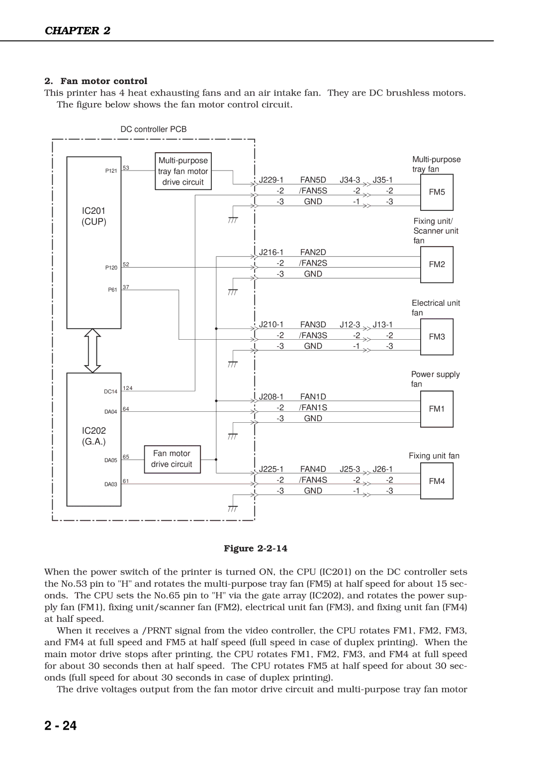
This printer has 4 heat exhausting fans and an air intake fan. They are DC brushless motors. The figure below shows the fan motor control circuit.
| DC controller PCB |
|
|
|
|
| |
|
|
|
|
|
| ||
P121 | 53 | tray fan motor |
|
|
|
| tray fan |
| FAN5D | ||||||
|
| drive circuit |
| ||||
|
|
| /FAN5S | FM5 | |||
IC201 |
|
| GND |
| |||
|
|
|
|
|
|
| |
(CUP) |
|
|
|
|
|
| Fixing unit/ |
|
|
|
|
|
|
| Scanner unit |
|
|
|
|
|
|
| fan |
|
|
| FAN2D |
|
|
| |
P120 | 52 |
| /FAN2S |
|
| FM2 | |
|
| GND |
|
|
| ||
|
|
|
|
|
| ||
P61 | 37 |
|
|
|
|
|
|
|
|
|
|
|
|
| |
|
|
|
|
|
|
| Electrical unit |
|
|
|
|
|
|
| fan |
|
|
| FAN3D |
| |||
|
|
| /FAN3S | FM3 | |||
|
|
| GND |
| |||
|
|
|
|
|
|
| Power supply |
DC14 | 124 |
|
|
|
|
| fan |
|
|
|
|
|
| ||
|
| FAN1D |
|
|
| ||
|
|
|
|
|
| ||
DA04 | 64 |
| /FAN1S |
|
| FM1 | |
|
|
| GND |
|
|
| |
IC202 |
|
|
|
|
|
|
|
(G.A.) |
|
|
|
|
|
|
|
DA05 | 65 | Fan motor |
|
|
|
| Fixing unit fan |
| drive circuit |
|
|
|
|
| |
|
| FAN4D |
| ||||
|
|
|
| ||||
DA03 | 61 |
| /FAN4S | FM4 | |||
|
|
| GND |
| |||
Figure
When the power switch of the printer is turned ON, the CPU (IC201) on the DC controller sets the No.53 pin to "H" and rotates the
When it receives a /PRNT signal from the video controller, the CPU rotates FM1, FM2, FM3, and FM4 at full speed and FM5 at half speed (full speed in case of duplex printing). When the main motor drive stops after printing, the CPU rotates FM1, FM2, FM3, and FM4 at full speed for about 30 seconds then at half speed. The CPU rotates FM5 at half speed for about 30 sec- onds (full speed for about 30 seconds in case of duplex printing).
The drive voltages output from the fan motor drive circuit and
2 - 24