CHAPTER 1
IV. PARTS OF THE PRINTER
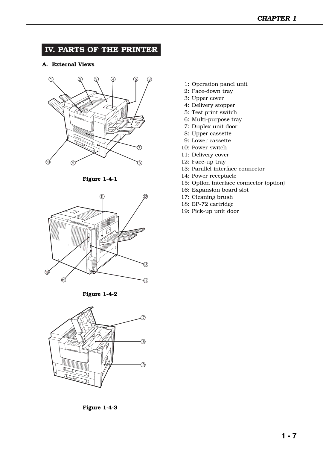
A. External Views
1 | 2 | 3 | 4 | 5 | 6 |
7
10 | 9 | 8 |
Figure
1112
13
16
15 | 14 |
Figure
17
18
19
Figure
1:Operation panel unit
2:
3:Upper cover
4:Delivery stopper
5:Test print switch
6:
7:Duplex unit door
8:Upper cassette
9:Lower cassette
10:Power switch
11:Delivery cover
12:
13:Parallel interface connector
14:Power receptacle
15:Option interface connector (option)
16:Expansion board slot
17:Cleaning brush
18:
19:
1 - 7