CHAPTER 3
B.Video Controller PCB Unit
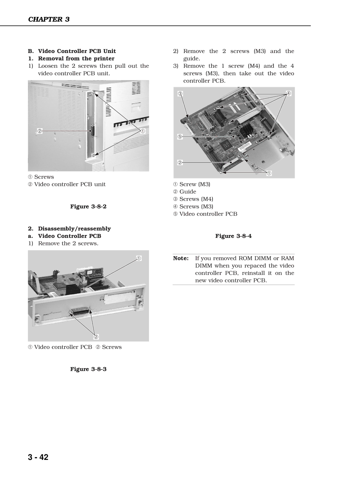
1. Removal from the printer
1)Loosen the 2 screws then pull out the video controller PCB unit.
➁ | ➀ |
➀Screws
➁Video controller PCB unit
Figure
2. Disassembly/reassembly a. Video Controller PCB
1) Remove the 2 screws.
➀
➁
➀Video controller PCB ➁ Screws
Figure
2)Remove the 2 screws (M3) and the guide.
3)Remove the 1 screw (M4) and the 4 screws (M3), then take out the video controller PCB.
➂ | ➃ |
➄
➁
➀
➀Screw (M3)
➁ Guide
➂ Screws (M4)
➃ Screws (M3)
➄ Video controller PCB
Figure
Note: If you removed ROM DIMM or RAM DIMM when you repaced the video controller PCB, reinstall it on the new video controller PCB.
3 - 42