CHAPTER 2
Step 2 Scanning exposure
Laser beam
Unexposed area
Exposed area
Figure
When the laser beam scans the drum surface, it causes the charge to be neutralized in the areas struck by the laser beam. These areas on the drum surface form the electrostatic latent image.
2. Development stage
Particles of toner are placed onto the electrostatic latent image on the surface of the drum to cre- ate a visible image. This printer uses the toner projection development method with a single- component toner.
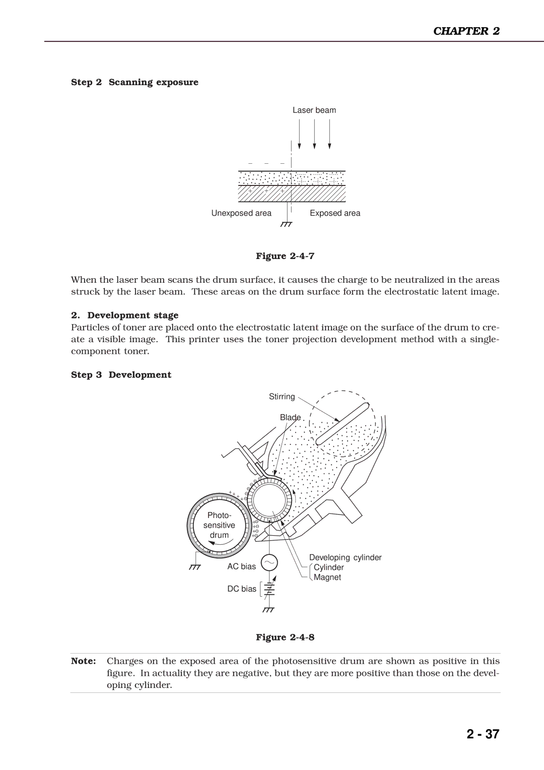
Step 3 Development
Stirring
Blade
Photo- sensitive drum
AC bias | Developing cylinder |
Cylinder | |
| Magnet |
DC bias |
|
Figure
Note: Charges on the exposed area of the photosensitive drum are shown as positive in this figure. In actuality they are negative, but they are more positive than those on the devel- oping cylinder.
2 - 37