CHAPTER 2
D.Power Supply
1. Outline
Power supply
Circuit | Noise |
| To fixing roller heater | DC controller |
| |||
breaker | filter |
|
|
|
|
|
|
|
|
|
|
|
|
|
| +3.3V | Video |
|
|
|
|
|
|
| +5V | |
|
|
|
|
|
|
| controller PCB | |
Current |
|
|
| Triac |
| +5V |
| |
transfor |
|
|
|
| Laser driver | |||
|
|
|
|
| ||||
|
|
|
|
|
|
| ||
Power |
|
|
|
|
|
|
|
|
switch |
|
| Inverter control |
|
|
|
|
|
(S101) |
|
|
|
|
|
|
| |
|
| circuit | Triac | Phototriac |
| +5V |
| |
| Relay |
|
| BD PCB | ||||
|
|
|
| coupler |
|
| ||
|
|
|
|
|
|
|
| |
Current |
|
|
| Phototriac |
| FSRTH |
|
|
fuse | Rectificat |
| Phototriac | coupler | Safety | +5V |
| |
| RLD | Sensors | ||||||
| ion circuit |
| coupler |
| circuit |
| ||
|
|
|
| /FSRD1 |
|
| ||
Rectificat |
|
|
|
|
|
|
| |
|
|
|
|
| /FSRD2 |
|
| |
ion circuit |
|
|
|
|
| /FSRDE |
|
|
|
|
|
|
|
|
|
| |
|
|
|
|
|
| /FSRCT | +5V | Operation |
Noise |
| Phototriac |
| SUPSLT |
| panel | ||
filter |
| detection circuit | coupler | Heater | /RLDSNS |
|
| |
|
|
|
|
| TSWIN |
|
| |
|
|
| t |
| drive |
|
| |
|
|
|
| TSWOUT | +24VA | Scanner | ||
|
|
|
| circuit | ||||
|
|
|
|
|
| |||
Converter |
|
|
|
|
|
| motor | |
|
|
|
|
|
|
| ||
Rush curren |
|
|
|
|
|
|
|
|
prevention |
|
| Switching | Filter | +24V | +24VB | ||
circuit |
|
|
| power supply | ||||
|
| FET | circuit |
|
| |||
Switching |
|
|
|
|
| |||
|
|
|
|
|
|
|
| |
FET |
| Rectificat |
|
|
|
|
| |
Filter | Transformer | ion filter |
|
| /REMT24 | +24VA | Solenoids | |
circuit | circuit |
|
|
| ||||
|
|
|
|
| ||||
|
|
|
|
|
| +5V |
| Clutches |
Switching |
|
|
|
|
|
|
| |
|
|
|
|
|
|
|
| |
FET |
|
|
|
|
|
|
|
|
|
|
| Switching | Filter |
| +3.3V | +24VB |
|
Transformer |
|
| FET | circuit |
|
| Main motor | |
|
|
|
|
| ||||
Control | +5V control |
| Current |
|
|
|
|
|
photocoupler | and |
|
|
|
| Switch | ||
IC |
|
| voltage |
|
|
|
| /sensor |
|
|
| detection |
|
|
|
| PCB |
|
|
| circuit |
|
|
|
| Door |
|
|
|
|
|
|
|
| |
|
|
|
|
|
|
|
| switch |
| Abnormal |
|
|
|
| +24VB | (SW1401) | |
| voltage latch |
|
|
|
| |||
| photocoupler |
|
|
| +24VA |
| ||
|
|
|
|
|
|
| ||
|
|
| Figure |
|
|
|
| |
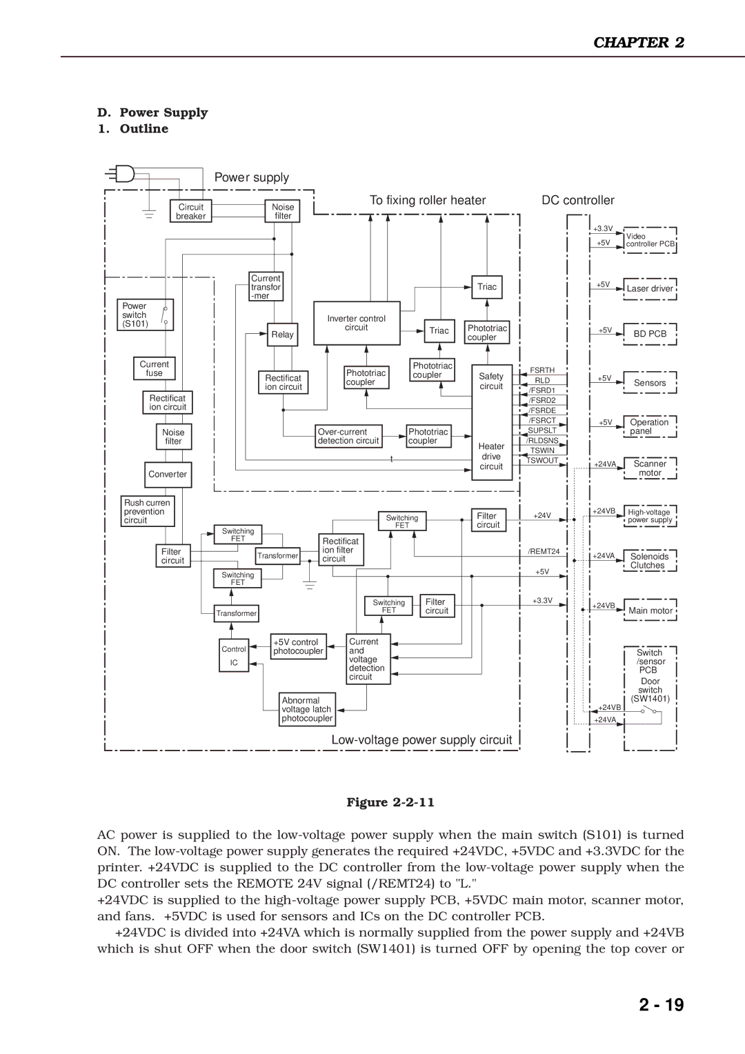
AC power is supplied to the
+24VDC is supplied to the
+24VDC is divided into +24VA which is normally supplied from the power supply and +24VB which is shut OFF when the door switch (SW1401) is turned OFF by opening the top cover or
2 - 19
