CHAPTER 3
b.Removal of RAM DIMM/ROM DIMM (option)
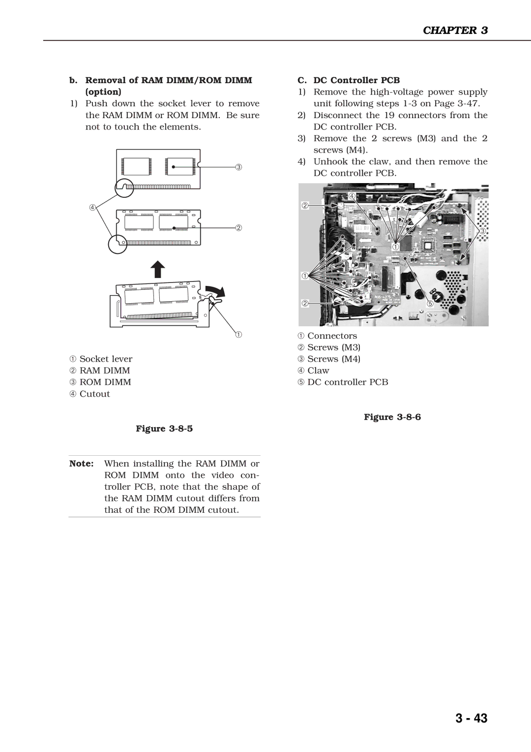
1)Push down the socket lever to remove the RAM DIMM or ROM DIMM. Be sure not to touch the elements.
➂
➃
➁
➀
➀Socket lever
➁ RAM DIMM
➂ ROM DIMM
➃ Cutout
Figure
Note: When installing the RAM DIMM or ROM DIMM onto the video con- troller PCB, note that the shape of the RAM DIMM cutout differs from that of the ROM DIMM cutout.
C. DC Controller PCB
1)Remove the
2)Disconnect the 19 connectors from the DC controller PCB.
3)Remove the 2 screws (M3) and the 2 screws (M4).
4)Unhook the claw, and then remove the DC controller PCB.
➃
➁
![]() ➂
➂
➀
➀ |
➁ | ➄ |
➀Connectors
➁ Screws (M3)
➂ Screws (M4)
➃ Claw
➄ DC controller PCB
Figure
3 - 43