CHAPTER 3
D.Upper Cassette
1)Remove the cassette
E. Thermistor
1)Remove the fixing unit following steps
2)Remove the wire cover.
3)Remove the fixing entry guide.
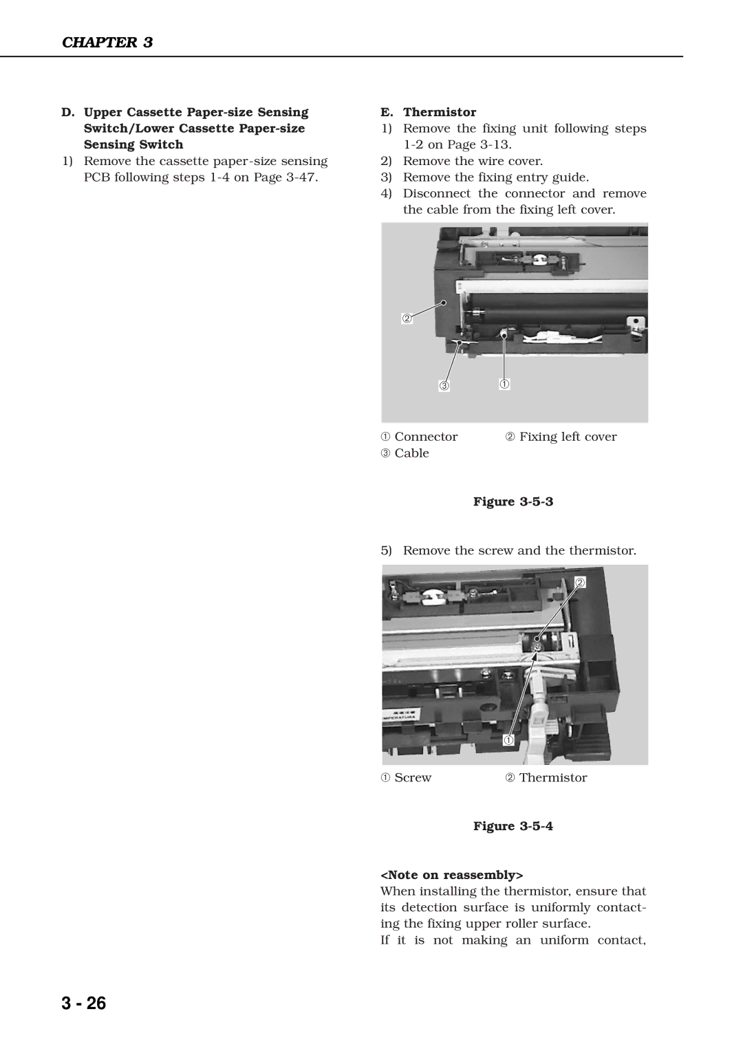
4)Disconnect the connector and remove the cable from the fixing left cover.
➁
➂➀
➀Connector ➁ Fixing left cover
➂ Cable
Figure
5)Remove the screw and the thermistor.
➁
➀
➀ Screw | ➁ Thermistor |
Figure
<Note on reassembly>
When installing the thermistor, ensure that its detection surface is uniformly contact- ing the fixing upper roller surface.
If it is not making an uniform contact,
3 - 26