CHAPTER 4
b. Confirming Printer Status
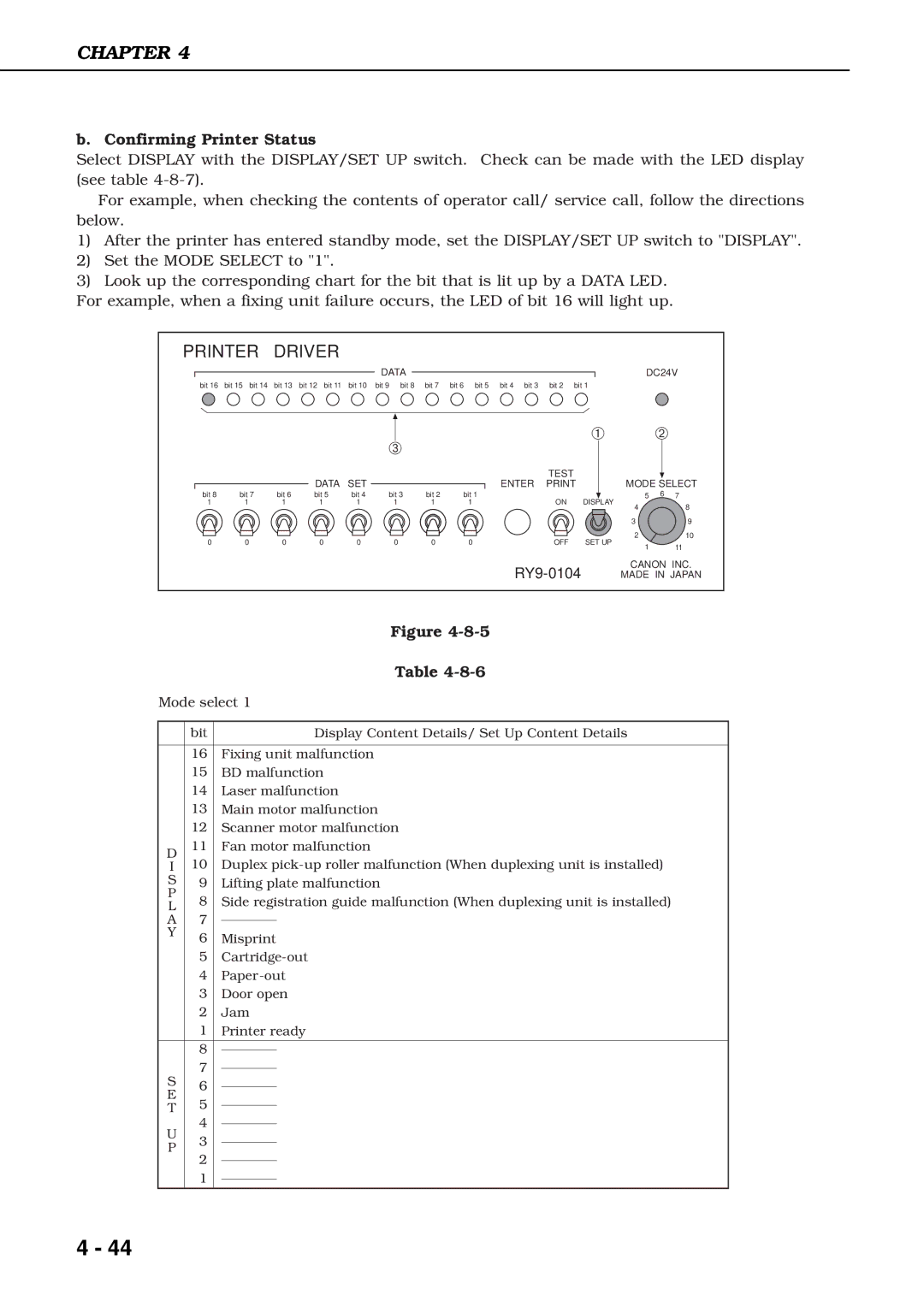
Select DISPLAY with the DISPLAY/SET UP switch. Check can be made with the LED display (see table
For example, when checking the contents of operator call/ service call, follow the directions below.
1)After the printer has entered standby mode, set the DISPLAY/SET UP switch to "DISPLAY".
2)Set the MODE SELECT to "1".
3)Look up the corresponding chart for the bit that is lit up by a DATA LED.
For example, when a fixing unit failure occurs, the LED of bit 16 will light up.
PRINTER DRIVER
bit 16 bit 15 bit 14 bit 13 bit 12 bit 11 bit 10
|
|
| DATA | SET |
bit 8 | bit 7 | bit 6 | bit 5 | bit 4 |
1 | 1 | 1 | 1 | 1 |
0 | 0 | 0 | 0 | 0 |
DATA |
|
|
| DC24V |
bit 9 bit 8 bit 7 bit 6 bit 5 bit 4 bit 3 | bit 2 bit 1 | |||
➂ |
|
|
| ➀ |
| ➁ | |
|
|
|
|
|
| ||
|
|
| TEST |
|
|
| |
|
| ENTER |
| MODE SELECT | |||
bit 3 | bit 2 | bit 1 | ON | DISPLAY | 5 | 6 7 | |
1 | 1 | 1 | 4 | 8 | |||
|
|
|
|
| |||
|
|
|
|
| 3 | 9 | |
0 | 0 | 0 | OFF | SET UP | 2 | 10 | |
1 | 11 | ||||||
|
|
|
|
| |||
|
|
|
| CANON INC. | |||
|
|
| MADE IN JAPAN | ||||
|
|
|
| Figure |
|
|
|
| Table |
Mode select 1 | ||||
|
|
|
|
|
| bit |
|
| Display Content Details/ Set Up Content Details |
|
|
|
|
|
| 16 |
| Fixing unit malfunction | |
| 15 |
| BD malfunction | |
| 14 |
| Laser malfunction | |
| 13 |
| Main motor malfunction | |
| 12 |
| Scanner motor malfunction | |
D | 11 |
| Fan motor malfunction | |
I | 10 |
| Duplex | |
S | 9 |
| Lifting plate malfunction | |
P | 8 |
| Side registration guide malfunction (When duplexing unit is installed) | |
L |
| |||
A | 7 |
|
|
|
|
|
| ||
Y | 6 |
| Misprint | |
|
| |||
| 5 |
| ||
| 4 |
| ||
| 3 |
| Door open | |
| 2 |
| Jam | |
| 1 |
| Printer ready | |
|
|
|
|
|
| 8 |
|
|
|
|
|
|
| |
S | 7 |
|
|
|
|
|
| ||
6 |
|
|
| |
E |
|
|
| |
5 |
|
|
| |
T |
|
|
| |
|
|
| ||
U | 4 |
|
|
|
|
|
| ||
3 |
|
|
| |
P |
|
|
| |
|
|
| ||
2 |
|
|
| |
|
|
|
| |
|
|
|
| |
| 1 |
|
|
|
|
|
|
| |
|
|
|
|
|
4 - 44