CHAPTER 2
Fixing unit/ |
|
|
|
| FAN1D | ||
|
|
|
| ||||
FAN1 |
|
|
| /FAN1S | |||
Scanner unit |
|
|
| ||||
|
|
| |||||
fan |
|
|
|
|
| ||
|
|
|
|
|
| ||
|
|
|
|
| FAN2D | ||
Power supply |
|
|
|
| |||
FAN2 |
|
|
| /FAN2S | |||
fan |
|
|
| ||||
|
|
|
|
| |||
|
|
| FAN3D | ||||
Electrical unit |
|
| |||||
FAN3 |
| /FAN3S | |||||
fan |
| ||||||
|
|
| |||||
|
|
| FAN4D | ||||
|
|
| |||||
Fixing unit fan | FAN4 |
| /FAN4S | ||||
| |||||||
|
|
|
| ||||
|
|
| FAN5D | ||||
|
| ||||||
FAN5 | o | /FAN5S | |||||
tray fan | |||||||
|
|
| |||||
|
|
|
|
|
| +24VA | |
Registration |
|
|
| ||||
CL1 |
|
| |||||
clutch |
| /REGCLD | |||||
|
|
|
|
| |||
|
|
|
|
| |||
|
| FEDAD | |||||
|
|
| |||||
Paper |
|
| FEDAND | ||||
SMT1 |
| ||||||
motor |
| FEDBD | |||||
|
| ||||||
|
|
| FEDBND | ||||
|
|
|
|
|
| ||
|
|
|
|
|
| +24VA | |
Cassette feed | SL1 |
|
|
|
| ||
|
| ||||||
solenoid |
| /PUPSLD | |||||
|
|
|
|
| |||
Feed clutch | CL2 |
|
|
|
| ||
| /FEEDCLD | ||||||
|
|
|
|
|
| ||
|
|
| Figure |
| |||
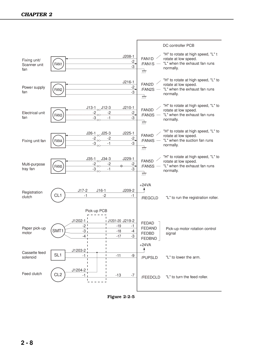
DC controller PCB
"H" to rotate at high speed, "L" t rotate at low speed.
"L" when the exhaust fan runs normally.
"H" to rotate at high speed, "L" to rotate at low speed.
"L" when the exhaust fan runs normally.
"H" to rotate at high speed, "L" to rotate at low speed.
"L" when the exhaust fan runs normally.
"H" to rotate at high speed, "L" to rotate at low speed.
"L" when the suction fan runs normally.
"H" to rotate at high speed, "L" to rotate at low speed.
"L" when the exhaust fan runs normally.
"L" to run the registration roller.
"L" to lower the arm.
"L" to turn the feed roller.
2 - 8