Page
Page
Page
Preface
Page
Table of Contents
Troubleshooting
Keypad and Start Up
Parameters
Appendix a Specifications Appendix B Accessories
Fault Code Information and Maintenance
Page
Appendix C How to Select the Right AC Motor Drive
This page intentionally left blank
Introduction
Receiving and Inspection
Nameplate Information
Model Explanation
Series Number Explanation 007EL23A 0T 7
Drive Frames and Appearances
25-2HP/0.2-1.5kW Frame a 5HP/0.75-3.7kW Frame B
RFI Jumper Location
Internal Structure
Remove Instructions
Preparation for Installation and Wiring
RFI Jumper
Remove Front Cover Remove Fan
Operation
Ambient Conditions
Storage
Transportation
Frame B Mounting Clearances
Installation with Metal Separation
Frame a Frame B
This function is not for 115V models
Frame
Dimensions
Introduction
Installation and Wiring
Wiring
For models of VFD-EL Series
MI1
NPN mode with external power
PNP mode with external power
Excellent Good
FUSE/NFB
External Wiring
Mains power terminals R/L1, S/L2, T/L3
Terminal Symbol
Main Circuit Main Circuit Connection
Explanation of Terminal Function
Output terminals for main circuit U, V, W
Terminals +, for connecting brake resistor
Main Circuit Terminals
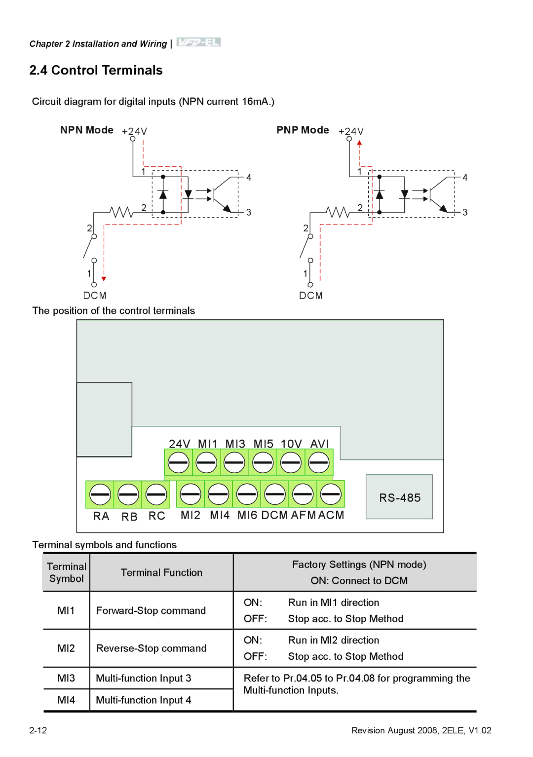
Control Terminals
NPN Mode +24V PNP Mode +24V
MI6
General
Analog inputs AVI, ACM
RA RB RC MI2 MI4 MI6 DCM AFM ACM
This page intentionally left blank
Description of the Digital Keypad
Keypad and Start Up
Descriptions
Display Message
To shift data
How to Operate the Digital Keypad
Operation Method
Trial Run
Frequency Source
Method
RUN
Parameters
Summary of Parameter Settings
Parameter Explanation Settings Factory Customer
Parameter Explanation Settings Factory Customer
Parameters
UP/DOWN
Parameter Explanation Settings Factory Customer
Setting
Parameter Explanation Settings Factory
Read only Relay
Parameter Explanation Settings Factory Customer
Group 5 Multi-Step Speed Parameters Explanation Settings
Parameter Explanation Settings
Group 6 Protection Parameters Explanation Settings
Parameter Explanation Settings Factory Customer
Group 7 Motor Parameters Explanation Settings Factory
Group 8 Special Parameters Explanation Settings Factory
Parameter Explanation Settings Factory Customer
Parameter Explanation Settings Factory
Parameter Explanation Settings Factory Customer
Parameter Explanation Settings Factory Customer
Parameter Explanation Settings Factory Customer
Parameter Settings for Applications
Wire
Two-wire/three-wire Applications Purpose
Operation Command Applications Purpose
Frequency Hold Applications Purpose
Parameters
Parameters
Parameters
00.02 Parameter Reset
Description of Parameter Settings
Group 0 User Parameters
115V/230V Series
Factory Setting
00.08
00.05
00.09
00.09 00.08
00.09
00.10 Reserved 00.11 00.12 50Hz Base Voltage Selection
00.13
00.14
01.01
01.00
01.02
01.03
01.05
01.06
01.07
01.09
01.08
01.10
01.11
01.13
01.14
01.15
01.13 01.14
Acceleration/deceleration Characteristics
Group 2 Operation Method Parameters
Combination of the First and Second Master Frequency Command
115V/230V/460V Series
02.03
2kHz
Source Pr.02.01 is changed
OFF Stop
02.08
02.07
02.11
02.12
02.15
Display Value Bit
Function
02.18
02.19
Group 3 Output Function Parameters
Settings Function Description
03.02
03.04
03.06
03.05
03.08
03.11
03.12
Parameters
04.00
Group 4 Input Function Parameters
04.02
Example 1 Standard application
Example 3 Use of bias and gain for use of full range
Example 5 Use of negative bias in noisy environment
REV
04.12
04.11
04.13
04.14
Analog input
Settings Function No Function Description
Master Frequency and Jog Frequency to select for
Speed. There are 17 step speed frequencies including
Application
Done while the motor is stopped. Refer to parameter
Settings Function
04.09
Function Description
04.10
Digital Terminal Input Debouncing Time Unit 2 msec Settings
04.27
Bit
04.28
Weights =internal terminal Bit
05.01
05.00
05.02
05.03
05.13 05.14
MI6=4 MI5=3 MI4=2 MI3=1
06.00
Group 6 Protection Parameters
06.02
06.01
Over-current stall prevention during operation
06.04
06.05
06.07
Factor %
Parameters
Parameters
07.00
Group 7 Motor Parameters
07.01
07.02
07.11
07.10
07.12
07.14
Resistor-divider
07.15
07.16
07.13
08.00
Group 8 Special Parameters
08.01
08.02
08.05
08.07
08.09
08.08
08.10
08.11
08.16
Setting frequency
AVR function disabled for stop
08.20
08.19
09.00
Group 9 Communication Parameters
09.03
Ascii mode
Bit Bit character Bit character frame
RTU mode
Bit Bit character Bit character frame Even
Start
Command message
6FH
Data content 17H 70H
Address 01H Function 03H Starting data address 21H 02H
Parameters
Parameters
Content
C3H
Communication program of PC
Exception Code
09.07
OutportbPORT+IER,0x01
RS485 BUS
Group 10 PID Control
10.11
10.02
10.03
10.04
10.05
10.07
10.06
10.12
10.10
10.13
10.14
10.16
10.18
10.21
10.22
10.23
10.24
10.25
10.26
10.33
10.27
Over Current OC
Troubleshooting
Over Voltage OV
Ground Fault
Low Voltage Lv
Overload
Over Heat OH1
Keypad Display is Abnormal
Phase Loss PHL
Motor cannot Run
Motor Speed cannot be Changed
Motor does not Run as Expected
Motor Stalls during Acceleration
Environmental Condition
Electromagnetic/Induction Noise
Affecting Other Machines
Common Problems and Solutions
Fault Code Information
Fault Fault Descriptions Corrective Actions Name
Over current
GFF hardware error OC hardware error
CC current clamp OV hardware error
Overheating
Low voltage
External Fault
Fault Descriptions Corrective Actions Name
Phase error
OV or LV Temperature sensor error
Analog signal error
Communication Error
PID feedback signal error
Phase Loss
Maintenance and Inspections
Reset
Daily Inspection
Periodic Inspection
Voltage Maintenance Check Items Methods and Criterion
Keypad Maintenance Check Items Methods and Criterion
Main circuit Maintenance Check Items Methods and Criterion
Change of copper plate
One
Year
Daily
Appendix a Specifications
Appendix a Specifications
Enviromental
This page intentionally left blank
All Brake Resistors & Brake Units Used in AC Motor Drives
Appendix B Accessories
Appendix B Accessories
VFD Series
Dimensions and Weights for Brake Resistors
Order P/N BR500W030, BR500W100, BR1KW020, BR1KW075
Appendix B Accessories
Phase Recommended Model
No Fuse Circuit Breaker Chart
Breaker a
Recommended no-fuse breaker
Fuse Specification Chart
AC Output Reactor Recommended Value
AC Reactor AC Input Reactor Recommended Value
~5% impedance
Impedance
M1 reactor AC motor drive Motor
Applications
Silicon Controlled Rectifier
Zero Phase Reactor RF220X00A
Diagram a
Diagram B
5 4 16 15 14 13 11 RC-01Terminal block
Remote Controller RC-01
Explanation of Display Message
PU06 Description of the Digital Keypad VFD-PU06
XX-XX
Operation Flow Chart
Setting baud rate
Wiring and Settings
Switch Baud Value Rate
Setting MAC addresses
Power Supply
LEDs Display
LonWorks Communication Module CME-LW01 B.8.2.1 Introduction
LED Indications
Specifications
Profibus Communication Module CME-PD01 Panel Appearance
Profibus Address
Parameters Settings in VFD-EL
Product Profile
CME-COP01 CANopen
Address Meaning
CANopen Connection
Components
Environmental Specifications
Communication
Pin Definition on CANopen Connection Port
MAC ID Setting
LED Indicator Explanation & Troubleshooting
Error LED
MKE-EP & DIN Rail
DIN Rail MKEL-DRA Only for frame a
Related Specification
Appendix C How to Select the Right AC Motor Drive
When one AC motor drive operates one motor
When one AC motor drive operates more than one motor
Capacity Formulas
⋅ IM ≤ the rated current of AC motor drive a
General Precaution
Parameter Settings Note
Selection Note
Standard motor
How to Choose a Suitable Motor
Pole-changing Dahlander motor
Special motors
Motor torque
Power Transmission Mechanism
This page intentionally left blank