Chapter 4 Parameters
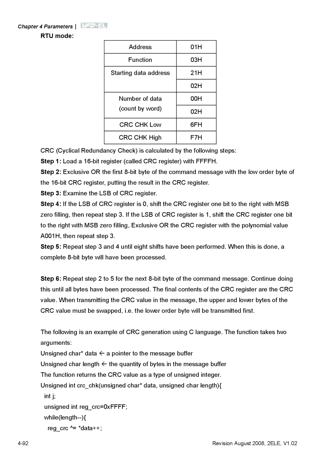
RTU mode:
Address | 01H | |
|
| |
Function | 03H | |
|
| |
Starting data address | 21H | |
|
| |
| 02H | |
|
| |
Number of data | 00H | |
(count by word) |
| |
02H | ||
| ||
|
| |
CRC CHK Low | 6FH | |
|
| |
CRC CHK High | F7H | |
|
|
CRC (Cyclical Redundancy Check) is calculated by the following steps: Step 1: Load a
Step 2: Exclusive OR the first
Step 3: Examine the LSB of CRC register.
Step 4: If the LSB of CRC register is 0, shift the CRC register one bit to the right with MSB zero filling, then repeat step 3. If the LSB of CRC register is 1, shift the CRC register one bit to the right with MSB zero filling, Exclusive OR the CRC register with the polynomial value A001H, then repeat step 3.
Step 5: Repeat step 3 and 4 until eight shifts have been performed. When this is done, a complete
Step 6: Repeat step 2 to 5 for the next
The following is an example of CRC generation using C language. The function takes two arguments:
Unsigned char* data Å a pointer to the message buffer
Unsigned char length Å the quantity of bytes in the message buffer The function returns the CRC value as a type of unsigned integer. Unsigned int crc_chk(unsigned char* data, unsigned char length){
int j;
unsigned int reg_crc=0xFFFF;
reg_crc ^= *data++;
Revision August 2008, 2ELE, V1.02 |