I7000
Equipment damage may occur
Word Definition Rwarning
Shock may occur
Risk or personal injury, fire or electric
Illustrations
Front panel
7MAIN Dial Dial 8RECEIVE/TRANSMIT Indicators RX/TX
Power Indicator Programmable Function Keys F-1/F-2
Microphone HM-151
Precautions
Table of Contents
SSB/CW/RTTY/AM only ……………………
Transmit filter width setting SSB only ………
Hz tone burst ………………………………
NR Level ……………………………………
Operation………………………………………… AH-4 operation ………………………………
From the TNC …………………………………
Specifications …………………………
General ………………………………………… Transmitter………………………………………
Panel Description
MENU/GROUP Keys MENU/GRP p
Twin PBT M-ch/RIT Indicator Pgs , 79, 88
Panel Description
TUNER/CALL KEY TUNER/CALL
4UP/DOWN Band Keys YBAND/ZBAND
1AUTO NOTCH/VOICE Recorder KEY ANF/ REC
2SPCH/LOCK KEY SPCH/LOCK
7MAIN Dial Dial
9TUNING Step KEY TS pgs
@2FUNCTION Display
Menu M-2 functions
Multi-function keys
Menu M-1 functions
Menu M-3 functions
Function
FM Tone Operation
Dtmf Operation
Menu S-1 functions
Menu S-2 functions
Select Scan
Menu G-1 Scope functions
Menu S-3 functions
Sweep Speed
⁄2TRANSMIT Frequency Check XFC
Power Indicator
⁄1VFO/MEMORY Selection V/M
⁄3TUNER/CALL KEY TUNER/CALL
Microphone connector
Microphone Connector Information
Rear panel
Data socket
ACC socket
Frequency Readout
When connecting the ACC conversion cable OPC-599
Function display
Meter Readouts
@01/4 Function Indicator
Appears when the preamp is on
Appears when the 12 dB attenuator is
7MULTI-FUNCTION Screen
Selecting a location
Installation and Connections
Unpacking
Antenna connection
Front panel separation
Installation
Stand
Front panel mounting
HM-151
Required connections
Ground p
Remot E p 4 p
Advanced connections
Spea KER p
Used for computer control and transceive Operation
Connecting a DC power supply
Power supply connections
Battery connections
Connecting the AH-4
External antenna tuners
MHz linear amplifier
Connecting the IC-PW1/EURO
Linear amplifier connections
OPC-599 conversion cable
Connections for CW
For no break-in operation
ACC Rtty EXT SP
When connecting to MIC connector
When connecting to Data socket
When connecting to ACC socket
Connections for packet
Menu resetting M-1
When first applying power CPU resetting
Initial settings
Basic Operation
VFO description
Differences between VFO and memory mode
VFO Mode
Example
Selecting VFO A/VFO B
Selecting VFO/memory mode
VFO operation
VFO equalization
Selecting an operating band
Using the band stacking registers
Band Register
Direct frequency entry with the microphone’s keypad
Frequency setting
Tuning with the main dial
Push F-INP/ENT
Push TS momentarily to turn the programmable tuning step on
Programmable tuning step
Rotate Dial for normal tuning, if desired
Selecting kHz step
MHz quick tuning step FM/WFM/AM only
Selecting 1 Hz or 10 Hz step SSB/CW/RTTY only
⁄4 tuning function CW/RTTY only
Select M-3
Push ZMENU/GRP twice to return to the normal operating mode
Volume setting
Auto tuning step function
Push ZMENU/GRP twice to return the normal op- erating mode
Operating mode selection
Voice synthesizer function
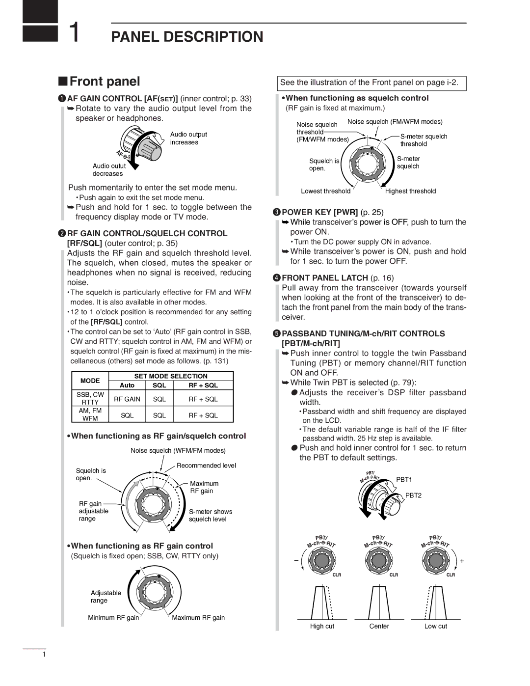
When functioning as squelch control RF gain is
Setting Operation
When setting as RF gain/squelch control
Squelch and receive RF sensitivity
Quick entry
Meter function
Multi-function meter
Select S-1
Dial lock function
Lock functions
Basic transmit operation
Microphone lock function
Setting microphone gain
Setting output power
Band SSB/CW
Operating SSB
Receive and Transmit
Convenient functions for receive
About 5 MHz band operation USA version only
IC-7000 Tuning FCC Channel
Convenient functions for transmit
Transmit quality monitor p
Operating CW
Set CW setting in the keyer set mode S-1
0Stop keying to return to receive
Break-in function p Memory keyer function p
Push P.AMP/ATT momentarily to turn the pre- amp on or OFF
⁄4 function p
While M-3 is selected, push F-1BRK one or
Push ZMENU/GRP to exit the quick set mode
CW reverse mode
CW side tone function
CW pitch control
Electronic CW keyer
Memory keyer send menu
Pre-set characters can be sent using the memory
Select S-1 Push F-2KEY to enter the keyer send menu
Programming contents
DEditing a keyer memory
Number Style
Contest number set mode
Setting the contact serial number
Count UP Trigger
Keyer Repeat Time
Keyer set mode
Setting the electronic keyer
Dot/Dash Ratio
Paddle Polarity
Keyer set mode Rise Time
Paddle operation from MIC connector
Keyer Type
Display the Rtty decoder screen
Transmit a Send signal from your TNC
Operating Rtty FSK
Rotate Dial to simultaneously tune a desired sig- nal
Convenient functions for receive
Twin peak filter
Rtty reverse mode
Mode
Setting the decoder threshold level
Function for the Rtty decoder indication
Rtty Decode Usos
Rtty decode set mode
Rtty Decode New Line Code
Rotate Dial to select the desired frequency
Pre-setting for using Rtty terminal or TNC
Mark frequency
Shift width
Operating AM
DSP noise reduction p Auto notch filter p
Push NR/LEV to turn the DSP noise reduction
Amp on or OFF On and OFF
Operating FM
Preamp and attenuator p DSP noise reduction p
While M-3 is selected, push F-1 VOX to turn
Tone squelch operation
Push Mode one or more times to select FM mode Select M-3
Push F-3TON for 1 sec. to enter the FM tone set mode
Rotate Dial to set the desired subaudible tone frequency
Push ZMENU/GRP to exit the FM tone set mode
Tone scan operation
Push F-3TON once or twice to turn the Dtcs function on
Dtcs operation
Available tone codes
One-touch repeater function
Repeater operation
Push F-3TON to turn the repeater tone on
Repeater tone frequency
Push F-3TON once or twice to turn the tone en- coder on
Auto repeater function
Transmit frequency monitor check
Frequency range and offset direction
Turn the auto repeater function OFF in the miscel
Storing a non standard repeater
Select M-2
Dtmf memory encoder
Dtmf send menu
Dtmf speed
Push Mode to select FM mode. w Select S-1
Programming a Dtmf code
Push F-2DTM then ZMENU/GRP to select the Dtmf root menu
Rotate M-chinner control to select the desired TV channel
Push and hold Afset for 1 sec. to turn the TV mode on
TV channel operation
Rotate AF to set a suitable audio level
Skip channel setting
Push ZMENU/GRP to exit the channel frequency set mode
Channel frequency adjustment
Rotate Dial to adjust the channel frequency
Push F-3SET to set the channel frequency
Functions for Receive
Fix mode
Simple band scope
Push F-3FIX momentarily to select the center mode
Center mode
Scope set mode
Select G-1 Scope
Scope Size
Preamp and attenuator
Max Hold
Fast Sweep
RIT function
To reset the RIT frequency, push F-3CLR for 1 sec
To cancel the RIT function, push F-1RIT mo- mentarily again
Calculate function
AGC time constant selection
Setting the AGC time constant
AGC function
Selectable AGC time constant unit sec
If filter selection
If filter for WFM mode is fixed and cannot be changed
If filter selection
Select the desired mode. w Select M-1
Push F-3FIL for 1 sec. to enter filter set mode
FIlter passband width setting SSB/CW/RTTY/AM only
Select SSB, CW, Rtty or AM mode
If fIlter shape SSB/CW only
Twin PBT operation
PBT Operation Example
NB Level
Noise blanker set mode
Noise blanker
NB Width
Noise reduction
Noise reduction set mode
NR Level
Auto notch function
Mode While in CW and Rtty modes, push MNF/ADJ
Notch function
This transceiver has auto and manual notch func
Manual notch filter set mode
Manual notch function
Meter peak hold function
Erating mode
Voice squelch control function
Push ZMENU/GRP twice to return to normal op
Functions for Transmit
Adjusting the VOX function
VOX function
VOX Delay
Transmit filter width setting SSB only
VOX set mode VOX Gain
Anti-VOX
Semi break-in operation
Break-in delay setting
Break-in function
Full break-in operation
∂TX function
To reset the ∂TX frequency, push F-3CLR for 1 sec
To cancel the ∂TX function, push F-2∂TX mo- mentarily again
Rotate RIT outer control to shift the transmitter frequency
Monitor function
Speech compressor
Select Comp meter Select S-1
Compression level setting
Comp Level
Push F-3MET one or more times to select the Comp meter
Direct Shift Frequency Input
Split frequency operation
Select VFO a and set the frequency to 21.290 MHz USB
Push F-1SPL M-1 on the transceiver’s front panel
Menu selection Example M-1
Quick split function
Push F-INP/ENT,, 5 then F-1 SPL M-1
Erating mode
Split offset frequency setting
Quick split setting
Rotate Dial to set the desired split offset
Spot measurement
Measuring SWR
Menu selection Example S-1
Plot measurement
Recording a received audio
Voice Recorder Functions
Digital voice recorder
Basic recording
Playing the recorded contents
Erasing the recorded contents
Push F-3REC again to stop recording
Recording a message for transmit
Recording
Push ZMENU/GRP twice to exit the voice mem- ory screen
Input the desired character by rotating Dial
Programming a memory name for transmit
Spaces can be used. See the step t below
Push ZMENU/GRP to input and set the name
Select S-1 Push F-1VO to call up the voice recorder menu
Transmit level setting
Sending a recorded message
Push F-1T1 F-4T4 to transmit the con- tents
Voice set mode Auto Monitor
Voice set mode
MIC Memo
Memory channel selection
Memory Operation
Memory channels
Memory Transfer Over Channel Capability Clear
Memory programming
Programming in VFO mode
Set the desired frequency and operating mode in VFO mode
Rotate M-chto select the desired memory chan- nel
Programming in memory mode
Set the desired frequency and operating mode
Selecting a memory channel using the memory channel list
Memory channel list
Selecting a memory bank
Setting a memory channel as a select memory
Memory channel list indication
Memory names
Editing programming memory names
Memory clearing
Memory clearing using the memory channel list
To return to VFO mode, push F-4V/M again
Frequency transferring
Transferring in VFO mode
Select a memory channel with M-ch
Transferring in memory mode
Push F-4V/M momentarily to select the VFO mode
Memo pads
Writing frequencies and operating modes into memo pads
Calling up a frequency from a memo pad
Scan types
Scan Operation
Preparation
Programmed scan operation
Memory scan operation
Select memory scan operation
Priority watch
Optional AT-180 Automatic Antenna Tuner operation
Manual tuning
Antenna Tuner Operation
Tuner operation
AH-4 operation
PTT tune function
Packet Operation
Adjusting the data speed
Adjusting the transmit signal output from the TNC
Packet operation
Clock and Timers
Time set mode
Setting the current date
Setting the current year
Setting the current time
Set the desired power-off time using Dial
Clock2 offset setting
Auto power OFF activity
Push ZMENU/GRP twice to exit timer set mode
SET Mode
Set mode description
Mode Set mode item Default setting RF Power
Quick set mode
SSB TBW Wide L SSB mode
RF Power all modes
SSB TBW MID H SSB mode
SSB TBW Wide H SSB mode
SSB TBW MID L SSB mode
SSB TBW NAR L SSB mode
Twin Peak Filter Rtty mode
Side Tone Level CW mode
Side Tone Level Limit CW mode
Rtty Mark Frequency Rtty mode
Display set mode
Display Font Size
12 1Hz Mode Popup
Display Font Type
Meter Peak Hold
Voice TX Name Display
TV Popup CH Up/Down
TV Popup P.AMP/ATT
Keyer Memory Display
My Call
Power on Check
Push ZMENU/GRP twice to exit the set mode screen
Opening screen example
Miscellaneous others set mode
Split Offset
RF/SQL Control
Quick Split
DUP Offset HF
One Touch Repeater
DUP Offset 144M
DUP Offset 430M
Auto Repeater
Vsend Select
Tuner Switch
Tuner PTT Start
Speech Level
Memopad Numbers
Speech Mode Switch
Speech S-Level
Scan Speed
31 HM-151 F-2
34 SSB/CW Synchronous Tuning
30 HM-151 F-1
MIC Up/Down Speed
Mode Select Rtty
Mode Select SSB
Mode Select CW
CW Normal Side
Mode Select WFM
Mode Select AM
Mode Select FM
External Keypad Voice
CI-V Baud Rate
REF Adjust
Front Keypad Type
CI-V Address
Memory backup
Maintenance
Fuse replacement
Cleaning
Troubleshooting
Est Icom Dealer or Service Center
Transmit Display Scan Problem Possible Cause Solution
Option Units Setting
MB-106CARRYING Handle
AT-180 inside top cover
AT-180 internal switch description
Connector information for ACC2 socket
Specifications for the AT-180
Remote jack CI-V information
Control Command
Command table
CI-V connection example
Control Command
146
147
Codes for memory keyer contents
To send/read memory contents
Band stacking register
Repeater tone/tone squelch frequency Setting
Codes for memory name contents
Split/Duplex frequency setting
Dtcs code and polarity setting
Specifications
General
Options
MB-62
OPC-1444
OPC-1443
OPC-589
Main menu group Sub menu group
Menu Guide
Graphic menu group
Set mode description
Memo
Memo
Intended Country of Use