Thank you, and congratulations on your choice of the Roland
Important Safety Instructions
Page
Page
Memory Backup
Power Supply
Placement
Maintenance
Contents
Creating Patches
Creating Rhythm Sets 168
Error Messages
Waveform List
Sample Playback Function Lets You Add Waves
Powerful Internal Effects, Including Cosm Effects
Voice Polyphony and 32- Part Multitimbrality
Create Amazingly Expressive Tones
Patch Finder
Front Panel
SYSTEM/UTILITY
Exit
User
Preset
Tone Switch
Patch
Rear Panel
Scsi Connector
Panel Descriptions DIF OUT Connector
Preview 1-4 Note Number
Setting the Way In Which Sounds Are Previewed
Preview Mode
Auditioning Sounds on the XV-5080 Phrase Preview
Playing a Patch on
Setting the XV-5080’s Midi Reception Channels
EXP Expansion
Selecting Sound Libraries
Selecting Patches by Category Patch Finder
Basic Procedure for Selecting a
Selecting a Patch
Patch
Following categories can be selected Category
Internal organization
Patch or Rhythm Set modes
Selecting Patches and Rhythm
Sets from an External Midi
Device
Performances
Performance mode
Rhythm Sets
Selecting How a Patch Will Play Polyphonic Monophonic
Setting a Patch’s Pitch Octave Steps Octave Shift
Turning Effects On/Off
Patch Mode Settings
Output Assign
Using the XV-5080 Effects
Split Key Edit Mode
Routing Tones to Effects
Making Chorus Settings
Making Multi-Effects Settings
For Type 1 Chorus
For Type 2 Delay
For Type 2 SRV ROOM/3 SRV HALL/4 SRV Plate
Making Reverb Settings
For Type 1 Reverb
HF Damp Gain -36-0 dB
LF Damp Gain -36-0 dB
HF Damp Freq LF Damp Frequency *3
Performance
Performance Mode Settings
Routing Part Outputs
Chorus Source PRF/P1-32
MFXA-C Control 1-4 Source
MFXA-C Control Destination
MFXA-C Control 1-4 Sens -63- +63
Using the XV-5080 Effects For Type 2 Delay
Reverb Source
For Type 2 SRV ROOM/3 SRV HALL/4 SRV Plate
Rhythm Set Mode Settings
Rhythm Tone Reverb Send Level
Rhythm Tone Output Assign
Rhythm Tone Dry Send Level
Rhythm Tone Chorus Send Level
Making Chorus Settings
Making Reverb Settings
Using the XV-5080 Effects For Type 1 Reverb
Parameters for Each Multi- Effects
Settings in General Midi Mode
Please refer to Making Effects Settings F5 Effects p
Keyboard Effects useful for the keyboard
Delay Effects that delay the sound
Modulation Effects that modulate the sound
Chorus Effects that broaden the sound
Dimension Effects that control the location Sound
LoFi Effects that intentionally degrades the sound quality
Guitar and Bass Effects useful for the Guitar and Bass
Overdrive
Using the XV-5080 Effects Stereo EQ Stereo Equalizer
Distortion
Phaser
Phaser
Distortion
Enhancer
Spectrum
Gain
Enhancer
Rotary
Auto WAH
Limiter
Compressor
Compressor
Limiter
Tremolo Chorus
HEXA-CHORUS
Filter
Phase
SPACE-D
Stereo Chorus
Flanger
Stereo Flanger
Step Rate
Stereo Delay
Delay
Step Flanger
Modulation Delay
Phase
Center Center Level Left Left Level Right Right Level
Triple TAP Delay
Delay Level
Modulation
Level
Quadruple TAP Delay
Pitch shift
Time Control Delay
22 2VOICE Pitch Shifter
Pitch a
Pitch
Pitch B
Level Balance
FBK Pitch Shifter
Gated Reverb
Reverb
Reverb
OVERDRIVE→ Chorus
OVERDRIVE→ Flanger
DISTORTION→ Flanger
OVERDRIVE→ Delay
DISTORTION→ Delay
DISTORTION→ Chorus
ENHANCER→ Flanger
ENHANCER→ Chorus
CHORUS→ Delay
ENHANCER→ Delay
Balance #
FLANGER→ Delay
CHORUS→ Flanger
CHORUS/FLANGER
CHORUS/DELAY
FLANGER/DELAY
42KEYSYNC Flanger
41STEREO Phaser
43FORMANT Filter
Keysync
Ring Modulator
44RING Modulator
Pan
45MULTI TAP Delay
Delay Time
Level
Threshold
46REVERSE Delay
Feedback
HF Damp
483D Delay
47SHUFFLE Delay
Pch Fine
493VOICE Pitch Shifter
Pch Coarse
Post Filter
50LOFI Compress
Lo-Fi
Pre Filter
Speaker
Radio Noise
Disc Noise
52SPEAKER Simulator
Tone
53OVERDRIVE
54DISTORTION
56STEREO Limiter
55STEREO Compressor
58SLICER
57GATE
603D Chorus
59ISOLATOR
613D Flanger
Auto Pan
62TREMOLO
63AUTO PAN
Mix Level Mix Level
Stereo Phaser
Switch Step Switch
ST Formant Filter Stereo Formant Filter
Stereo Auto WAH
Thres
Multi TAP Delay
Delay Level
HF Damp 1
Reverse Delay
Shuffle Delay
Feedback 1, 4 #
Right Delay Level Right
70 3D Delay
Center Delay Level Center
Left Delay Level Left
Spread
Rotary
Overdrive/Distortion
Rotary Multi
Mid
Sequence
Keyboard Multi
Pitch Shifter
Chorus/Flanger
Rhodes Multi
Spectrum
Tremolo/Pan
JD Multi
Stereo Lofi Compress
Noise
Stereo LO-FI Noise
Hum
Amp Tone
Guitar AMP Simulator
Amp Level
Stereo Distortion
Switch Amp Simulator Switch
Stereo Overdrive
Guitar Multi a
Amp Type Amp Simulator Type
Pre Delay Chorus/Flanger Pre Delay Time
OD/Dist OD/Dist Switch
Guitar Multi B
Feedback
Wah
Wah Sw Wah Switch
Wah Wah Switch
Guitar Multi C
Clean Guitar Multi a
EQ M Gain EQ Mid Gain
HF Dump Delay HF Damp
Pre Dly Chorus/Flanger Pre Delay Time
100
101
Clean Guitar Multi B
Seqeuence
Amp Sim Amp Simulator
OD/Dist Overdrive or Distortion Switch
Bass Multi
102
Level Overdrive/Distortion Level #
Band EQ
103
Band Gain
Isolator
Boost/Cut
Stereo Spectrum
105
89 3D Auto Spin
Auto Spin
90 3D Manual
Copy Type
Copying Effect Settings
When Using 3D Effects
106
107
Signal Tone Flow
108
Parameters
Selecting Output Jacks
Patch Effects General page Patch F6 Effects F1 General
System General #1 page System F1 General Master
Patch Common General #1 page Patch F1 Common F1 General
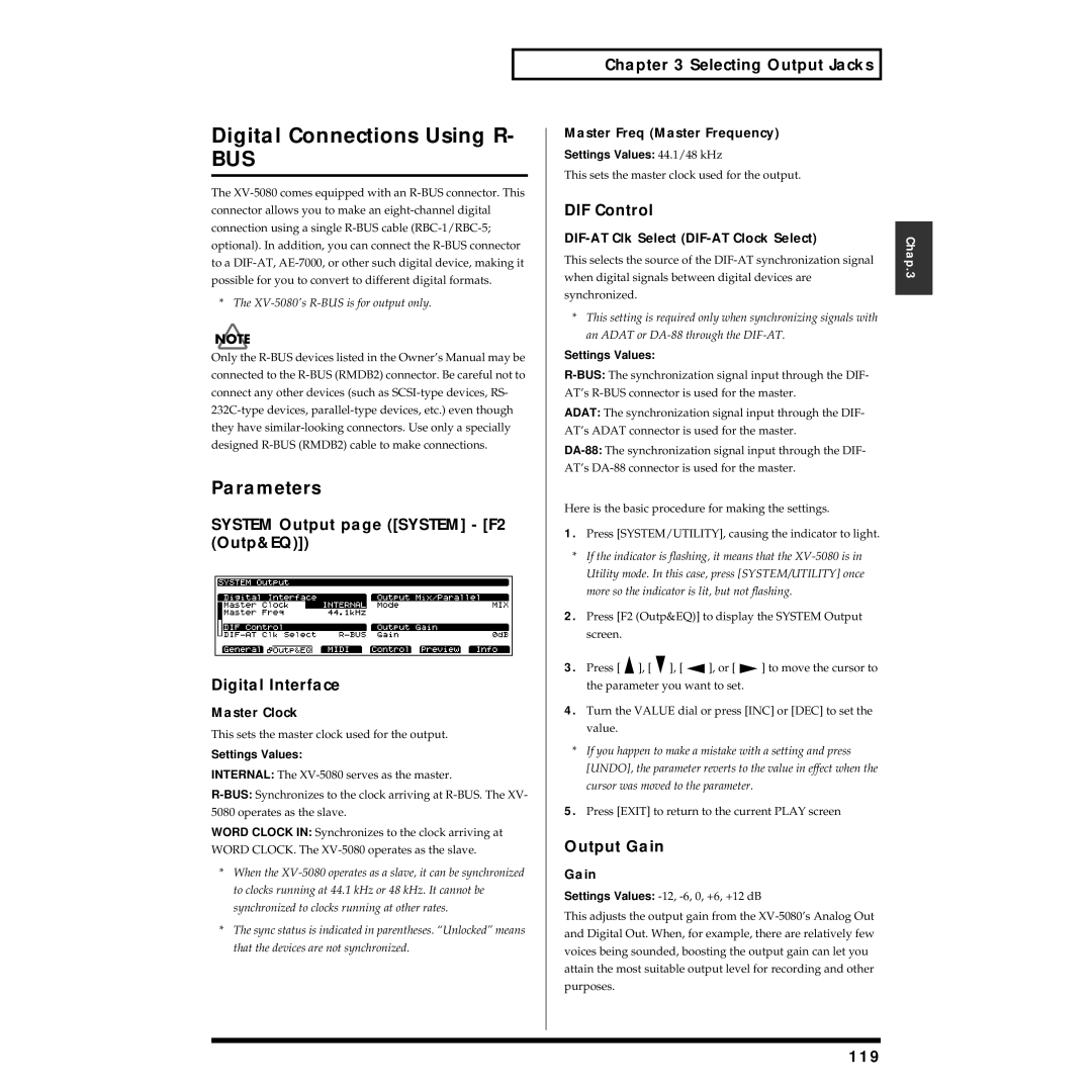
System Output page System F2 OutP&EQ Digital Interface
Output Mix/Parallel
110
Example of Settings
Part Output MFX Select
Signal Part Flow
Available Settings A-C
111
112
System Output page System F2 OutP&EQ Output Mix/Parallel
MFX-A
113
114
Signal Rhythm Tone Flow
Rhythm Effects General page Rhythm F6 Effects F1 General
Output Assign Rhythm Set Output Assign
Rhythm Common page Rhythm F1 Common
115
116
117
GM Effects General page GM F6 Effects F1 General
118
119
Digital Connections Using R
DIF Control
Output Gain
120
When Making the XV-5080 the Word Clock Master
When Making the XV-5080 the Word Clock Slave
Eight-Channel R-BUS Digital Connection
Digital Output to an Adat
When Making the XV-5080 the Word Clock Slave Settings
Settings
Converting to the Various Digital Formats
122
Digital Output to a Tascam DA Series
123
Digital Output to an AES/EBU Device
124
Synchronizing the XV-5080 to the Word Clock arriving at
125
Types of Patches and Their Composition
Four-Tone Patch
How a Tone Is Organized
Creating Patches
Selecting the Tones That Will Sound Tone On/Off
Multi-partial Patch
How a Partial Is Organized
127
Settings Common to the Entire Patch
Common Patch Common
Patch Common General #1 page Patch F1 General
128
Octave&Tune Patch Octave & Tune
Voice Priority
One Shot Mode
Control Patch Control
Tempo Patch Tempo
130
Bender
Portament Patch Portamento
Type Structure Type
Structure Patch Structure
131
132
Range Patch Key Range
TMT Keyboard Range Lower
TMT Keyboard Range Upper
Range Patch Velocity Range
Creating Patches TMT Velocity Fade Width Upper
Creating Four-Tone Patches
Tips for Creating a Patch
More Advanced Editing of Tones
135
Tips for Selecting a Waveform
Palette Function
136
Modifying the Waveform and Pitch F2 WG
Patch WG Parameter page Patch F2 WG F1 WG Prm
Wave
137
Tone Delay
FXM Frequency Cross Modulation
Patch WG Pitch Envelope page Patch F2 WG F3 Pch Env
Patch WG Pitch page Patch F2 WG F2 Pitch
Random Pitch Tone Random Pitch
Pitch Keyfollow Wave Pitch
Sample
Velocity Sens Pitch Envelope Velocity Sensitivity
Patch WG Sample page Patch
F2 WG F4 Sample
TVF
Using the Filter to Modify the Brightness F3 TVF
141
Resonance Velo TVF Resonance Velocity
Cutoff Keyfollow TVF Cutoff
Cutoff Velo TVF Cutoff Velocity
142
Velo Sens TVF Envelope Velocity Sensitivity
Velo Curve TVF Envelope Velocity Curve
TVA
Changing the Volume and Stereo Location F4 TVA
144
Patch TVA Envelope page Patch F4 TVA F2 TVA Env
Velocity Sens TVA Envelope Velocity Sensitivity
145
Delay LFO Delay
Applying Vibrato or Tremolo F5 LFO&CTL
Rate LFO Rate
146
Creating Patches Fade LFO Fade
Key Sync LFO Key Sync
Depth LFO Depth
147
Assigning Partials
Creating Multi-Partial Patches
Patch WG Parameter page Patch F2 WG F1 WG Prm Partial
Midi Midi Switch
Editing Partials
Assign Assign Type
Editing Samples
SMT Velocity Fade Width Upper
SMT Velocity Fade Width Lower
SMT Velocity Range Lower
SMT Velocity Range Upper
REV ONE Reverse One-shot
152
153
Cutoff
TVF Velo TVF Velocity
154
TVF Envelope
Velo Sens
Pitch Depth Envelope Pitch Depth
Creating Patches TVA Velo TVA Velocity
Making the Volume Change F4 TVA
Patch TVA Parameter page Patch F4 TVA F1 TVF Prm
Level
156
LFO2 *1
Key Sync
157
158
Making Effect Settings
Copying the Settings Another Patch Patch Tone
Saving Patches You Create
Choosing the Parts to Play
How a Performance Is Organized
Basic Ways to Use Performances
Solo Part Select
Establishing Settings for an Entire Performance Common
Settings for Each Part
Creating a Performance
161
Comparing the Settings of Each Part as You Make Settings
Setting the Keyboard Range
Performance 1 page Perform F3 Part Patch Part Patch
Creating a Performance Part Keyboard Range Lower
Part Keyboard Range Upper
Part Keyboard Fade Width Upper
163
Bend Range Part Pitch Bend Range
Voice Reserve Part Voice Reserve
Performance 2 page Perform F3 Part Modify Part Modify
Establishing a Part’s Midi Settings
165
Part Mute
Performance Part Information page Perform F6 Info
Copying the Settings Another Part Performance Part Copy
Saving Performances You Create
Confirming Midi Information for Each Midi Channel
Performance Name Copy
Editing a Patch or Rhythm Set in the Performance Mode
Palette Function
167
WG Wave Generator
How Percussion Instruments Are Organized
168
169
Settings Common to an Entire Rhythm Set
Creating Rhythm Sets
Tempo
170
Setting up Individual Rhythm Tones
Name Tone Name
Modifying the Waveform, Pan and Pitch F2 Key WG
Rhythm WG Parameter page Rhythm F2 WG F1 WG Prm Rhythm Tone
171
172
Tune
Gain & Level
173
Random Pitch Rhythm Tone Random Pitch
Rhythm WG Pitch Envelope page Rhythm F2 WG F3 Pch Env
WMT Velocity Fade Width Upper
WMT Velocity Fade Width Lower
WMT Velocity Range Lower
WMT Velocity Range Upper
175
Using the Filter to Modify Brightness F3 Key TVF
Rhythm TVF Parameter
Rhythm F3 Key TVF F1 TVF Prm
Range -63
176
Rhythm TVA Parameter page Rhythm F4 Key TVA F1 TVA Prm
Making the Volume Change F4 Key TVA
Rhythm TVF Envelope page Rhythm F3 Key TVF F2 TVF Env
Amount V-Crv TVF Envelope Velocity Curve
178
Pan
Rhythm TVA Envelope page Rhythm F4 Key TVA F2 TVA Env
Velocity Sens
179
Other Settings F5 Key Ctl
Saving the Rhythm Set You Create
Rhythm Key Control page Rhythm F5 Key Ctl
180
Copying Settings from Some Other Rhythm Tone
181
Installing the Simm Memory Module
Loading Sampler Libraries CD-ROM
Loading a Variety of Data
Confirming That the Simm Is Properly Installed
Simm Slot Installation Order
Removing SIMMs
183
Installation de la carte dextension Wave
184
Enlever une carte mémoire Wave
F5 Refresh
Connecting a CD-ROM Drive
With Sampler Libraries
185
Disk
Free Area
Marked
186
Case of the S-700 series
When Loading Libraries for the Akai S1000/3000
When Loading AIFF/WAV Libraries
About Each Sampler Library Folder Type Display
188
About the Display of Folder Categories in Sampler Libraries
Sample Load
Total
Target
Auto Load
189
190
Playing Back Loaded Sampler Libraries
Loading Data Saved on a Zip Disk
Individually Loading Patches, Performances, or Rhythm Sets
Transmitting Samples
Loading Data Stored on Memory Cards
Sample-Related Utilities
Sending and Receiving Samples Sample Dump
192
Receiving Samples
Processing
193
Automatically Creating Multi- Partial Patches Create Patch
194
Saving Edits to the XV- 5080’s Internal Memory Write
Saving Tones and Other Data You’ve Created
195
Before Using a Memory Card
Saving All Data to Memory Card Disk F2 Save
Saving Tones and Other Data You’ve Created
196
Formatting a Memory Card
Saving Data
Organizing the Contents of Memory Cards
198
Copying/Moving Files Cp/Move
199
Copying Files on One Memory Card to Another Card CardCpy
If the hard disk has not been partitioned
Saving All Data to Zip Disk Disk F2 Save
Formatting a Zip Disk/Hard Disk Format
200
Copying/Moving a File/Folder Cp/ Move
Organizing a Zip Disk
Renaming a File/Folder Rename
Deleting a File/Folder Delete
202
Initializing a Sound
For Patches or Performances
For Rhythm Sets
203
Transmitting Data to an External Midi Device Data Transfer
Transmitting to an External Midi Device
Midi
Source
Destination
Transmitting to User Memory
204
Exclusive Protect
Protecting the Internal Memory Protect
205
Internal Write Protect
206
Resetting All Settings to Default Factory Settings Factory
Directly registering to the list on the PATCH/RHYTHM Play
Registering Favorite Patches in the Favorite List
Selecting Patches from
207
208
Making Overall Settings
Setup
Setting the System Tempo
Making Scale Tune Settings SYSTEM/UTILITY F1 General
Setting the Tuning and Volume Settings
210
Setting In Performance/GM mode Key Scale
High Gain
Output-A 1/2-D 7/8 Low Frequency
Low Gain
High Frequency
Receive Switch
Setting the Midi Channel
Settings
Setting the Midi Transmit
213
Midi in connectors
Patch/Rhythm Set Mode
When GM on or GS Reset is received at Midi
214
Connecting Two or More XV- 5080s to Increase Polyphony
Mode Stack Mode
Stack
Simm
Battery Check
Selecting Common Controllers System Utility F4 Control
Confirming the Current Status SYSTEM/UTILITY F6 Info
XV-5080 Self
Scsi ID
216
MFX Control Sens -63- +63
Examples of Applications Using
217
MFX Control Source
218
Modifying Tone Settings
Examples of Applications Using
Modifying Multi-Effects to Match the System’s Tempo
Applications for Patches
Syncing the LFO Cycle to System
Tempo
220
Making a Tone’s Delay Time Match the System Tempo
Playing Phrase Loops at a System’s Tempo
221
Changing the Part Settings from an External Midi Device
222
What is RPN?
223
Applications for Matrix Control
Muting a Specific Part
Using the XV-5080 as a General Midi Sound Module
Entering GM Mode
Playing Back a GM Score
Control Modify Part Modify
Modifying GM Mode Settings
Settings for Playing Sounds F2
Turning Effects On/Off
Tune
Examples of Applications Using Key Mode
Portament Portamento
Level&Pan
227
Making Effects Settings F5 Effects
Part Midi
228
Utility Functions in GM Mode
Checking Midi Information for Each Part F6 Info
229
Transmitting GM Mode Settings Xfer
Initializing the GM Sound Generator Used in GM Mode F1 GM
230
231
Appendices
Pitch is wrong
Can’t select the Part for which to make settings
No sound
Can’t select Performances
Song data does not playback correctly
Effects do not apply
Midi messages are not received correctly
Memory Card cannot be used
234
Is any Scsi ID being used for more than one device?
Commercial sampler data for other devices cannot be loaded
There is no sound from the digital out, or there is noise
File Format Error
Battery Low
DISK, Read Error
DISK, Write Error
Memory Card I/O Error
Error Messages File Name Folder, VolumeFormat Error
File Read Error
File Write Error
Memory Card Write Protected
Memory Error
Midi Communication Error
Receive Data Error
Too Many Files
Error Messages Source Disk Incorrect
Unknown Disk Error
This Will Clear the Files/Folders.Are You Sure?
What you need to know before making connections
Connecting a Scsi device
Connection Examples
About Scsi ID Numbers
Making Connections
About Scsi
Patch Parameters
Patch WG Sample PATCH-F2WG-F4Samplep
Patch WG Parameter PATCH-F2WG-F1WG Prmp
Patch WG Pitch PATCH-F2WG-F2Pitchp
Patch WG Pitch Envelope PATCH-F2WG-F3Pch Envp
Patch TVA Envelope PATCH-F4TVA-F2TVA Envp
Parameter List Patch TVF Parameter PATCH-F3TVF-F1TVF Prmp
Patch TVF Envelope PATCH-F3TVF-F2TVF Envp
Patch TVA Parameter PATCH-F4TVA-F1TVA Prmp
244
Patch LFO&Ctrl #1 PATCH-F5LFO&CTL-F3Controlp
Patch LFO&Ctrl #2 PATCH-F5LFO&CTL-F3Controlp
Patch LFO&Ctrl Control Sw PATCH-F5LFO&CTL-F4Ctrl Swp
Patch Effects Reverb PATCH-F6Effects-F2Reverbp
Patch Effects MFX Control PATCH-F6Effects-F2MFX Prmp
Patch Effects MFX Control PATCH-F6Effects-F3MFX Ctlp
Patch Effects Chorus PATCH-F6Effects-F4Chorusp
Multi Partial Patch Parameters
247
Parameter List Patch TVF Envelope PATCH-F3TVF-F2TVF Envp
Patch LFO&Ctrl LFO PATCH-F5LFO&Ctl-F1LFO1p
Patch LFO&Ctrl Control #1 PATCH-F5LFO&Ctl-F2Controlp
248
Performance Parameters
250
Performance Midi #3 Midi Filter PERFORMANCE-F4MIDIp
251
Performance Effects Chorus PERFORMANCE-F5Effect-F4Chorusp
Performance Effects Reverb PERFORMANCE-F5Effect-F5Reverbp
Performance Part Information PERFORMANCE-F6 InfoP
Rhythm Set Parameters
Rhythm TVA Parameter RHYTHM-F4Key TVA-F1TVA Prmp
Rhythm WG Sample RHYTHM-F2Key WG-F5Samplep
Rhythm TVF Parameter RHYTHM-F3Key TVF-F1TVF Prmp
Rhythm TVF Envelope RHYTHM-F3Key TVF-F2TVF Envp
Rhythm Effects MFX Control RHYTHM-F6Effects-F3MFX Ctlp
Parameter List Rhythm Key Control RHYTHM-F5Key Ctlp
Rhythm Effects General RHYTHM-F6Effects-F1Generalp
Rhythm Effects MFX RHYTHM-F6Effects-F2MFX Prmp
GM Mode Parameters
256
Parameter List GM Effects General GM-F6Infop
3DISTORTIONp
Parameter List 4PHASERp
MFX Prameters 1STEREO EQp
2OVERDRIVEp
11HEXA-CHORUSp
Parameter List 8ROTARYp
9COMPRESSORp
10LIMITERp
15STEREO FLANGERp
17STEREO DELAYp
18MODULATION DELAYp
19TRIPLE TAP DELAYp
23FBK Pitch SHIFTERp
Parameter List 20QUADRUPLE TAP DELAYp
21TIME Control DELAYp
222VOICE Pitch SHIFTERp
33ENHANSER→
26OVERDRIVE→
27OVERDRIVE→
28OVERDRIVE→
39FLANGER/DELAYp
Parameter List 35CHORUS→ DELAYp
36FLANGER→ DELAYp
38CHORUS/DELAYp
44RING MODULATORp
45MULTI TAP DELAYp
46REVERSE DELAYp
43FORMANT FILTERp
50LOFI COMPRESSp
Parameter List 47SHUFFLE DELAYp
483D DELAYp
493VOICE Pitch SHIFTERp
54DISTORTION 2p
51LOFI NOISEp
52SPEAKER SIMULATORp
Parameter List 53OVERDRIVE 2p
603D CHORUSp
Parameter List 57GATEp
58SLICERp
59ISOLATORp
63AUTO PANp
64STEREO Phaser 2p
67MULTI TAP DELAYp
62TREMOLOp
71ROTARY 2p
Parameter List 68REVERSE Delay 2p
69SHUFFLE Delay 2p
703D Delay 2p
269
72ROTARY MULTIp
Parameter List 73KEYBOARD MULTIp
270
Parameter List 74RHODES MULTIp
75JD MULTIp
76STEREO Lofi COMPRESSp
80STEREO DISTORTIONp
77STEREO Lofi NOISEp
78GUITAR AMP SIMULATORp
79STEREO OVERDRIVEp
272
Parameter List 81GUITAR Multi Ap
82GUITAR Multi Bp
273
Parameter List 84CLEAN Guitar Multi Ap
83GUITAR Multi Cp
274
Parameter List 85CLEAN Guitar Multi Bp
86BASS MULTIp
87ISOLATOR 2p
275
88STEREO SPECTRUMp
893D Auto SPINp
903D MANUALp
System Parameters
277
Waveform List
PWM
Waveform List
278
MMM VOX
279
280
REV 909 Nzhh
281
Control Change
282
Polyphonic Key Pressure
283
Midi Implementation
284
285
Global Parameter Control
286
Sample Dump Standard
287
Data Transmission
288
Universal Non-realtime System Exclusive Message
289
290
Parameter address map
Performance
291
Performance Common MFX
292
Performance Common Chorus
293
Lower
294
TVA-ATK TVA-DCY, TVA-REL TMT FXM, MFX1 MFX2, MFX3, MFX4
295
Patch Common Reverb
296
127, MUSICAL-NOTES
297
Rhythm Common MFX
298
Rhythm Common Reverb
299
300
GS Model ID 42H
Part Parameter
301
Examples of actual Midi messages
302
Decimal and Hexadecimal table
Example of an Exclusive message and calculating a checksum
303
Ascii code table
Scale Tune Feature address 40 1x
304
RPN LSB, MSB
Nrpn LSB, MSB
306
307
Index
308
309
Africa
Information
Avis
02019812 ’02-6-F2-61K