6F3B0250
7.Instructions
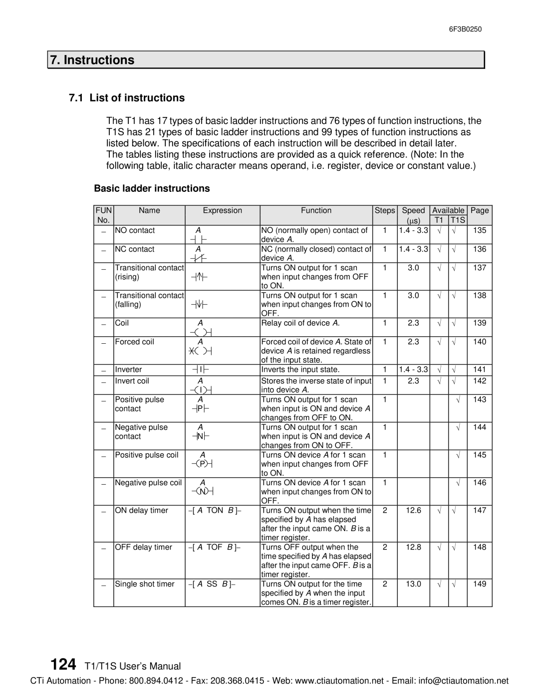
7.1List of instructions
The T1 has 17 types of basic ladder instructions and 76 types of function instructions, the T1S has 21 types of basic ladder instructions and 99 types of function instructions as listed below. The specifications of each instruction will be described in detail later.
The tables listing these instructions are provided as a quick reference. (Note: In the following table, italic character means operand, i.e. register, device or constant value.)
Basic ladder instructions
FUN | Name |
|
|
|
|
|
| Expression | Function | Steps | Speed | Available | Page | ||||||||
No. |
|
|
|
|
|
|
|
|
|
|
|
|
|
|
|
|
| (ms) | T1 | T1S |
|
- | NO contact |
|
|
|
| A | NO (normally open) contact of | 1 | 1.4 - 3.3 | Ö | Ö | 135 | |||||||||
|
|
|
|
|
|
|
|
|
|
|
|
|
|
|
| device A. |
|
|
|
|
|
|
|
|
|
|
|
|
|
|
|
|
|
|
|
|
|
|
|
|
|
| |
- | NC contact |
|
|
|
| A | NC (normally closed) contact of | 1 | 1.4 - 3.3 | Ö | Ö | 136 | |||||||||
|
|
|
|
|
|
|
|
|
|
|
|
|
|
|
| device A. |
|
|
|
|
|
|
|
|
|
|
|
|
|
|
|
|
|
|
|
|
|
|
|
|
|
| |
- | Transitional contact |
|
|
|
|
|
|
|
|
|
|
|
|
|
| Turns ON output for 1 scan | 1 | 3.0 | Ö | Ö | 137 |
| (rising) |
|
|
|
|
|
|
|
|
|
|
|
|
|
| when input changes from OFF |
|
|
|
|
|
|
|
|
|
|
|
|
|
|
|
|
|
|
|
|
|
|
|
|
| ||
|
|
|
|
|
|
|
|
|
|
|
|
|
|
|
| to ON. |
|
|
|
|
|
- | Transitional contact |
|
|
|
|
|
|
|
|
|
|
|
|
|
| Turns ON output for 1 scan | 1 | 3.0 | Ö | Ö | 138 |
| (falling) |
|
|
|
|
|
|
|
|
|
|
|
|
|
| when input changes from ON to |
|
|
|
|
|
|
|
|
|
|
|
|
|
|
|
|
|
|
|
|
|
|
|
|
| ||
|
|
|
|
|
|
|
|
|
|
|
|
|
|
|
| OFF. |
|
|
|
|
|
- | Coil |
|
|
|
| A | Relay coil of device A. | 1 | 2.3 | Ö | Ö | 139 | |||||||||
|
|
|
|
|
|
|
|
|
|
|
|
|
|
|
|
|
|
|
|
|
|
|
|
|
|
|
|
|
|
|
|
|
|
|
| ||||||||
- | Forced coil |
|
|
|
| A |
| Forced coil of device A. State of | 1 | 2.3 | Ö | Ö | 140 | ||||||||
|
|
|
|
|
|
|
|
|
|
|
|
|
|
|
| device A is retained regardless |
|
|
|
|
|
|
|
|
|
|
|
|
|
|
|
|
|
|
|
|
| of the input state. |
|
|
|
|
|
- | Inverter |
|
|
|
|
| I |
|
|
|
| Inverts the input state. | 1 | 1.4 - 3.3 | Ö | Ö | 141 | ||||
|
|
|
|
| |||||||||||||||||
|
|
|
|
|
| ||||||||||||||||
- | Invert coil |
|
|
|
| A | Stores the inverse state of input | 1 | 2.3 | Ö | Ö | 142 | |||||||||
|
|
|
|
|
|
| I | into device A. |
|
|
|
|
| ||||||||
- | Positive pulse |
|
|
|
| A | Turns ON output for 1 scan | 1 |
|
| Ö | 143 | |||||||||
| contact |
|
|
|
| P |
|
|
|
| when input is ON and device A |
|
|
|
|
| |||||
|
|
|
|
|
|
|
|
|
|
|
|
| |||||||||
|
|
|
|
|
|
|
|
|
|
|
|
|
|
|
| changes from OFF to ON. |
|
|
|
|
|
- | Negative pulse |
|
|
|
| A | Turns ON output for 1 scan | 1 |
|
| Ö | 144 | |||||||||
| contact |
|
|
|
| N |
|
|
|
| when input is ON and device A |
|
|
|
|
| |||||
|
|
|
|
|
|
|
|
|
|
|
|
| |||||||||
|
|
|
|
|
|
|
|
|
|
|
|
|
|
|
| changes from ON to OFF. |
|
|
|
|
|
- | Positive pulse coil |
|
|
|
|
| A | Turns ON device A for 1 scan | 1 |
|
| Ö | 145 | ||||||||
|
|
|
|
|
|
| P | when input changes from OFF |
|
|
|
|
| ||||||||
|
|
|
|
|
|
|
|
|
|
|
|
|
|
|
| to ON. |
|
|
|
|
|
- | Negative pulse coil |
|
|
|
|
| A | Turns ON device A for 1 scan | 1 |
|
| Ö | 146 | ||||||||
|
|
|
|
|
|
| N | when input changes from ON to |
|
|
|
|
| ||||||||
|
|
|
|
|
|
|
|
|
|
|
|
|
|
|
| OFF. |
|
|
|
|
|
- | ON delay timer | Turns ON output when the time | 2 | 12.6 | Ö | Ö | 147 | ||||||||||||||
|
|
|
|
|
|
|
|
|
|
|
|
|
|
|
| specified by A has elapsed |
|
|
|
|
|
|
|
|
|
|
|
|
|
|
|
|
|
|
|
|
| after the input came ON. B is a |
|
|
|
|
|
|
|
|
|
|
|
|
|
|
|
|
|
|
|
|
| timer register. |
|
|
|
|
|
- | OFF delay timer | Turns OFF output when the | 2 | 12.8 | Ö | Ö | 148 | ||||||||||||||
|
|
|
|
|
|
|
|
|
|
|
|
|
|
|
| time specified by A has elapsed |
|
|
|
|
|
|
|
|
|
|
|
|
|
|
|
|
|
|
|
|
| after the input came OFF. B is a |
|
|
|
|
|
|
|
|
|
|
|
|
|
|
|
|
|
|
|
|
| timer register. |
|
|
|
|
|
- | Single shot timer | Turns ON output for the time | 2 | 13.0 | Ö | Ö | 149 | ||||||||||||||
|
|
|
|
|
|
|
|
|
|
|
|
|
|
|
| specified by A when the input |
|
|
|
|
|
|
|
|
|
|
|
|
|
|
|
|
|
|
|
|
| comes ON. B is a timer register. |
|
|
|
|
|
124 T1/T1S User’s Manual
CTi Automation - Phone: 800.894.0412 - Fax: 208.368.0415 - Web: www.ctiautomation.net - Email: info@ctiautomation.net