6F3B0250
4. Installation and Wiring
4.2 Installing the unit
1. Improper installation directions or insufficient installation can cause fire
! CAUTION or the units to drop. Install the T1/T1S and related equipment in accordance with the instructions described in this section.
2.Turn off power before installing or removing any units, modules, racks or terminal blocks. Failure to do so can cause electrical shock or damage to the T1/T1S and related equipment.
3.Entering wire scraps or other foreign debris into to the T1/T1S and related equipment can cause fire or malfunction. Pay attention to prevent entering them into the T1 and related equipment during installation and wiring.
NOTE
The T1/T1S basic unit and the expansion unit come equipped with a bracket at the rear for mounting on a 35 mm DIN rail. However, no DIN rail bracket is provided on the expansion rack.
Installation precautions:
·Because the T1/T1S is not
·Do not install the unit directly above equipment that generates a large amount of heat, such as a heater, transformer, or
·Do not install the unit within 200 mm of a
·Allow at least 70 mm on all sides of the unit for ventilation.
·For safely during maintenance and operation, install the unit as far as possible from
·If a
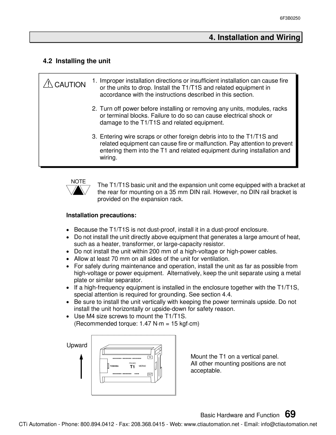
·Be sure to install the unit vertically with keeping the power terminals upside. Do not install the unit horizontally or
·Use M4 size screws to mount the T1/T1S. (Recommended torque: 1.47 N×m = 15 kgf×cm)
Upward
| PROSEC |
|
TOSHIBA | T1 | MDR40 |
IN
OUT
Mount the T1 on a vertical panel. All other mounting positions are not acceptable.
Basic Hardware and Function 69
CTi Automation - Phone: 800.894.0412 - Fax: 208.368.0415 - Web: www.ctiautomation.net - Email: info@ctiautomation.net