6F3B0250
7. Instructions
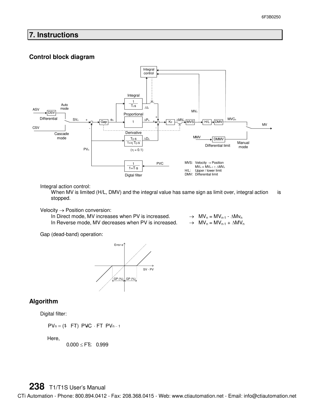
Control block diagram
|
|
|
|
|
| Auto |
|
| ||
ASV |
|
|
| mode |
|
| ||||
|
|
|
|
| DSV |
|
|
|
|
|
CSV | Differential |
|
| SVn | + | |||||
| ||||||||||
|
|
|
|
|
|
| - | |||
|
|
|
|
|
|
| ||||
|
|
|
|
|
|
|
|
| ||
|
|
|
|
| Cascade |
|
| |||
|
|
|
|
|
| mode |
|
| ||
|
|
|
|
|
|
|
|
|
| PVn |
Integral control
Integral |
|
1 |
|
TI×s | DIn |
|
|
|
| Proportional |
|
| + |
|
| |||||
|
| en |
| 1 |
|
| DPn | + |
|
| |||
|
|
|
|
|
|
|
|
| |||||
| Gap |
|
|
|
|
|
| KP | |||||
|
|
|
|
|
|
|
|
| |||||
|
|
|
|
|
|
| - |
| |||||
|
|
|
|
|
|
|
|
|
|
|
| ||
|
|
|
|
|
|
|
|
|
|
|
| ||
|
|
|
| Derivative |
|
| |||||||
|
|
|
|
|
|
|
|
|
| ||||
|
|
|
|
|
|
|
|
|
|
|
|
|
|
|
|
|
|
| TD×s |
| DDn |
|
|
|
|
| |
|
|
|
|
| 1+h×TD×s |
|
|
|
|
|
|
|
|
|
|
|
|
|
|
|
|
|
|
|
|
|
|
|
|
|
|
| (h = 0.1) |
|
|
|
|
|
| ||
|
|
|
|
|
|
|
|
|
| PVC | |||
|
|
| 1 |
|
|
|
|
| |||||
1+T×s
Digtal filter
|
|
|
|
|
| MVn |
|
|
|
|
|
|
|
|
| |||
D | MVn |
|
|
|
|
|
|
|
|
|
| MVCn |
|
| ||||
|
|
|
|
|
| MVS |
|
|
| H/L |
|
| DMV |
|
|
| MV | |
|
|
|
|
|
|
|
|
|
|
|
|
|
|
|
|
|
| |
|
|
|
|
|
|
|
|
|
|
|
|
|
|
|
|
|
| |
|
|
|
|
|
|
|
|
|
|
|
|
|
|
|
|
|
| |
|
|
|
|
|
| MMV |
|
|
|
|
|
|
| |||||
|
|
|
|
|
|
|
|
|
|
|
|
|
|
| ||||
|
|
|
|
|
|
|
|
|
|
|
|
|
|
| ||||
|
|
|
|
|
|
|
|
| DMMV |
|
|
| ||||||
|
|
|
|
|
|
|
|
|
|
|
|
|
| Manual | ||||
|
|
|
|
|
|
|
|
|
|
|
|
|
|
|
|
| ||
|
|
|
|
|
|
|
|
|
| Differential limit | ||||||||
|
|
|
|
|
|
|
|
|
| mode | ||||||||
|
|
|
|
|
|
|
|
|
|
|
|
|
|
|
|
| ||
|
|
|
| MVS: | Velocity ® Position |
|
| |||||||||||
|
|
|
|
|
|
| MVn = |
|
| |||||||||
|
|
|
| H/L: | Upper / lower limit |
|
| |||||||||||
|
|
|
| DMV: | Differential limit |
|
| |||||||||||
Integral action control:
When MV is limited (H/L, DMV) and the integral value has same sign as limit over, integral action is stopped.
Velocity ® Position conversion: | ® |
| - DMvn |
In Direct mode, MV increases when PV is increased. | MVn = | ||
In Reverse mode, MV decreases when PV is increased. | ® | MVn = | + DMVn |
Gap |
|
|
|
Error e |
|
|
|
SV - PV
![]()
![]() GP (%) GP (%)
GP (%) GP (%)
Algorithm
Digital filter:
PVn = (1- FT) ×PVC + FT ×PVn - 1
Here,
0.000 £ FT £ 0.999
238 T1/T1S User’s Manual
CTi Automation - Phone: 800.894.0412 - Fax: 208.368.0415 - Web: www.ctiautomation.net - Email: info@ctiautomation.net