|
| 6F3B0250 | |||
|
|
| |||
|
| 4. Installation and Wiring | |||
| 4.3 | Wiring terminals | |||
|
|
|
| ||
|
|
|
|
|
|
| ! | CAUTION 1. Turn off power before wiring to minimize the risk of electrical shock. | |||
2.Exposed conductive parts of wire can cause electrical shock. Use
3.Turn off power before removing or replacing units, modules, terminal blocks or wires. Failure to do so can cause electrical shock or damage to the T1/T1S and related equipment.
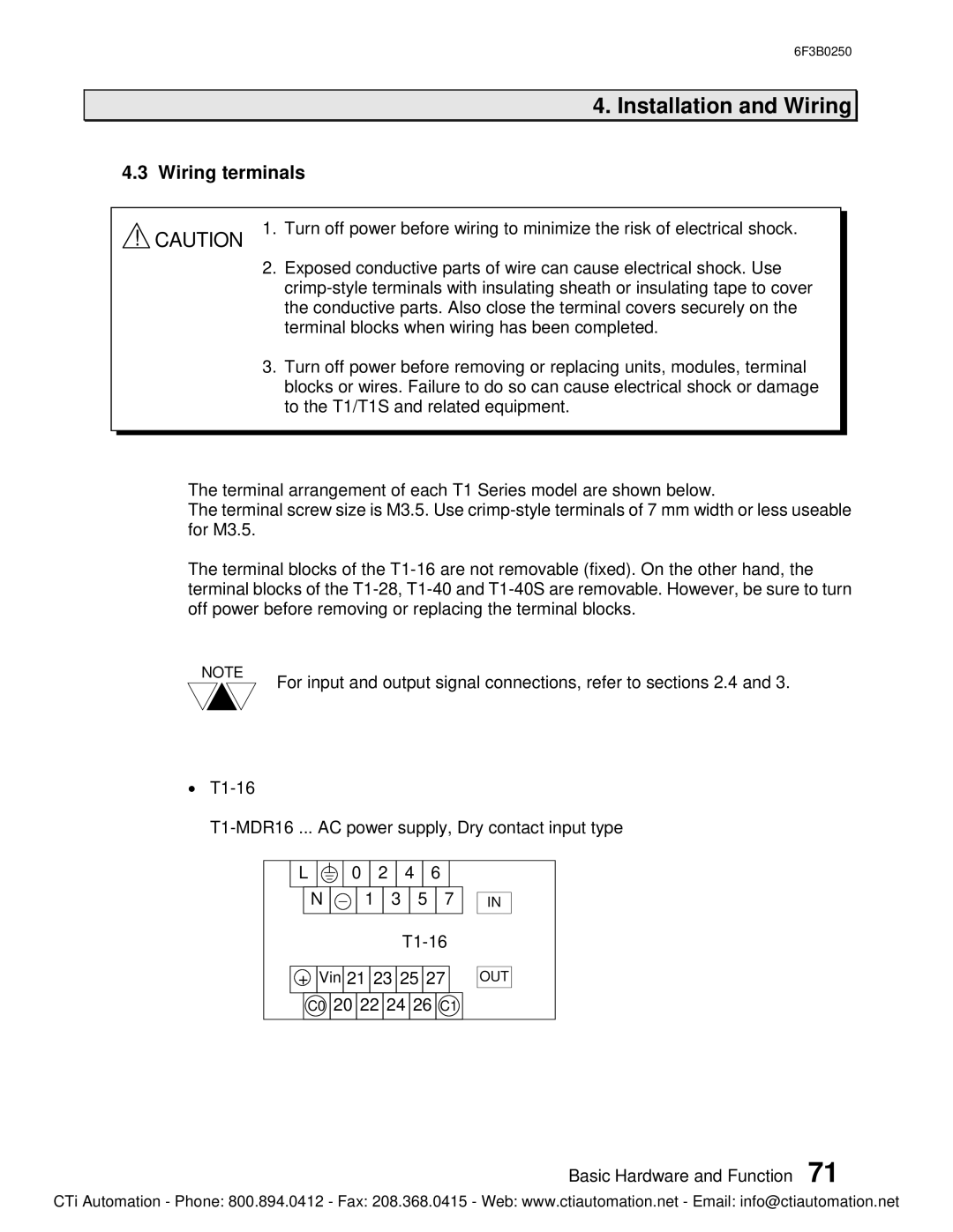
The terminal arrangement of each T1 Series model are shown below.
The terminal screw size is M3.5. Use
The terminal blocks of the
NOTE
For input and output signal connections, refer to sections 2.4 and 3.
·
L |
|
|
| 0 |
| 2 |
| 4 |
| 6 |
| |||||
|
|
|
|
|
|
|
|
|
|
|
|
|
|
|
|
|
|
| N | - |
| 1 |
| 3 | 5 |
| 7 | ||||||
|
|
|
|
|
|
|
|
|
|
|
|
|
| |||
|
|
|
|
|
|
|
|
|
|
| ||||||
|
|
|
| |||||||||||||
+ |
| Vin 21 23 25 27 | ||||||||||||||
C0 ![]() 20
20 ![]() 22
22 ![]() 24
24 ![]() 26
26 ![]() C1
C1
IN
OUT
Basic Hardware and Function 71
CTi Automation - Phone: 800.894.0412 - Fax: 208.368.0415 - Web: www.ctiautomation.net - Email: info@ctiautomation.net
