6F3B0250
3. I/O Application Precautions
(2)Minimum ON/OFF time of the input signal
The following conditions guarantee correct reading of the ON/OFF state of the input signal:
Input ON time: ON delay time + the time for one scan
Input OFF time: OFF delay time + the time for one scan
The ON and OFF times of the input signals must be longer than these intervals.
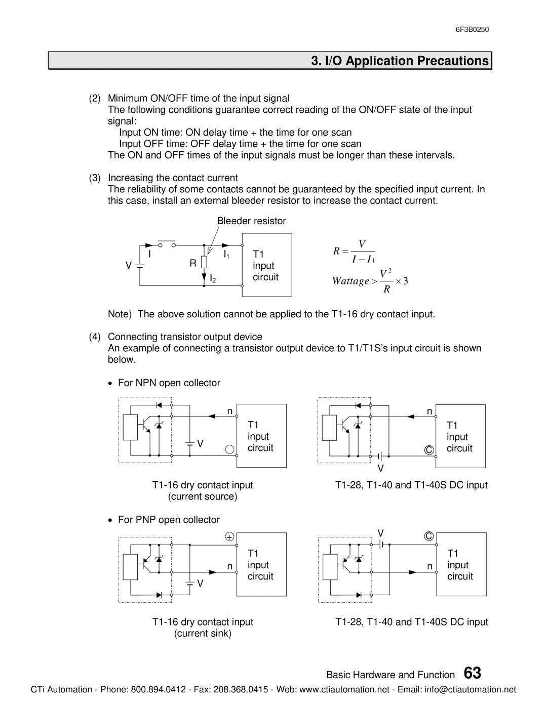
(3)Increasing the contact current
The reliability of some contacts cannot be guaranteed by the specified input current. In this case, install an external bleeder resistor to increase the contact current.
V
I
R
Bleeder resistor
I1 | T1 |
| input |
I2 | circuit |
R = V
I - I 1
Wattage > V 2 ´ 3
R
Note) The above solution cannot be applied to the
(4)Connecting transistor output device
An example of connecting a transistor output device to T1/T1S’s input circuit is shown below.
· For NPN open collector
| n | |
| T1 | |
V | input | |
circuit | ||
|
(current source)
·For PNP open collector
+
T1
n input
circuit
![]() V
V
(current sink)
n |
|
| T1 |
| input |
C | circuit |
V |
|
VC
T1
n input circuit
Basic Hardware and Function 63
CTi Automation - Phone: 800.894.0412 - Fax: 208.368.0415 - Web: www.ctiautomation.net - Email: info@ctiautomation.net