6F3B0250
7. Instructions
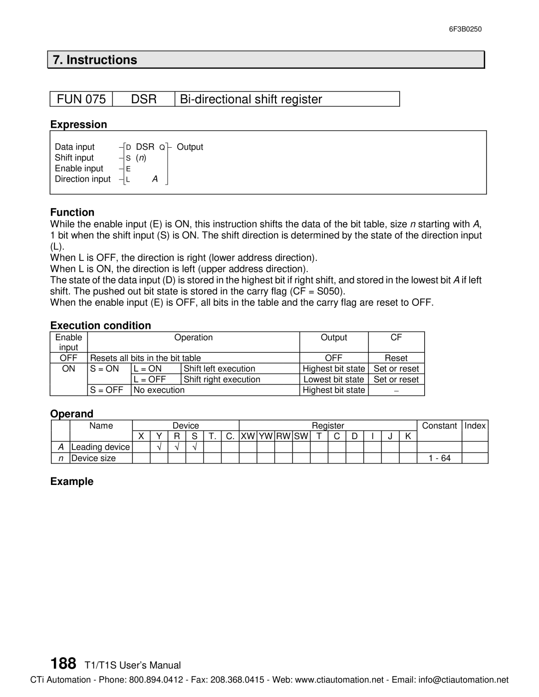
FUN 075
DSR
Bi-directional shift register
Expression
Data input | - |
| D DSR Q |
| - Output | |
|
| |||||
Shift input | - |
| S (n) |
|
|
|
Enable input | - |
| E |
|
|
|
Direction input | - |
| L | A |
| |
|
|
|
|
|
|
|
Function
While the enable input (E) is ON, this instruction shifts the data of the bit table, size n starting with A, 1 bit when the shift input (S) is ON. The shift direction is determined by the state of the direction input
(L).
When L is OFF, the direction is right (lower address direction). When L is ON, the direction is left (upper address direction).
The state of the data input (D) is stored in the highest bit if right shift, and stored in the lowest bit A if left shift. The pushed out bit state is stored in the carry flag (CF = S050).
When the enable input (E) is OFF, all bits in the table and the carry flag are reset to OFF.
Execution condition
Enable |
|
| Operation | Output | CF | |
input |
|
|
|
|
|
|
OFF | Resets all bits in the bit table | OFF | Reset | |||
ON | S = ON | L = ON |
| Shift left execution | Highest bit state | Set or reset |
|
| L = OFF |
| Shift right execution | Lowest bit state | Set or reset |
| S = OFF | No execution | Highest bit state | - | ||
Operand
| Name |
|
| Device |
|
|
|
|
|
| Register |
|
| Constant | Index | ||||
|
| X | Y | R | S | T. | C. | XW | YW | RW | SW | T | C | D | I | J | K |
|
|
A | Leading device |
| Ö | Ö | Ö |
|
|
|
|
|
|
|
|
|
|
|
|
|
|
n | Device size |
|
|
|
|
|
|
|
|
|
|
|
|
|
|
|
| 1 - 64 |
|
Example
188 T1/T1S User’s Manual
CTi Automation - Phone: 800.894.0412 - Fax: 208.368.0415 - Web: www.ctiautomation.net - Email: info@ctiautomation.net