6F3B0250
1. System Configuration
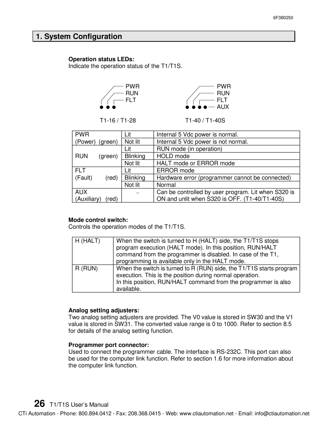
Operation status LEDs:
Indicate the operation status of the T1/T1S.
PWR | PWR |
RUN | RUN |
FLT | FLT |
| AUX |
| |||
|
|
|
|
PWR |
| Lit | Internal 5 Vdc power is normal. |
(Power) (green) | Not lit | Internal 5 Vdc power is not normal. | |
|
| Lit | RUN mode (in operation) |
RUN | (green) | Blinking | HOLD mode |
|
| Not lit | HALT mode or ERROR mode |
FLT |
| Lit | ERROR mode |
(Fault) | (red) | Blinking | Hardware error (programmer cannot be connected) |
|
| Not lit | Normal |
AUX |
| - | Can be controlled by user program. Lit when S320 is |
(Auxiliary) (red) |
| ON and unlit when S320 is OFF. | |
Mode control switch:
Controls the operation modes of the T1/T1S.
H (HALT) | When the switch is turned to H (HALT) side, the T1/T1S stops |
| program execution (HALT mode). In this position, RUN/HALT |
| command from the programmer is disabled. In case of the T1, |
| programming is available only in the HALT mode. |
R (RUN) | When the switch is turned to R (RUN) side, the T1/T1S starts program |
| execution. This is the position during normal operation. |
| In this position, RUN/HALT command from the programmer is also |
| available. |
Analog setting adjusters:
Two analog setting adjusters are provided. The V0 value is stored in SW30 and the V1 value is stored in SW31. The converted value range is 0 to 1000. Refer to section 8.5 for details of the analog setting function.
Programmer port connector:
Used to connect the programmer cable. The interface is
26 T1/T1S User’s Manual
CTi Automation - Phone: 800.894.0412 - Fax: 208.368.0415 - Web: www.ctiautomation.net - Email: info@ctiautomation.net