Atlas
Trademarks
To the Holder of the Manual
Configuration Guides
Network Turnup Procedure
Detail Level Procedures
About this Manual
MIB
Revision History
Safety Instructions
Save These Important Safety Instructions
Affidavit Requirements for Connection to Digital Services
ADTRAN, Inc Running H/F 1 doc title
Running H/F 1 doc title ADTRAN, Inc
REN FIC Usoc
Running H/F 1 doc title ADTRAN, Inc
ADTRAN, Inc Running H/F 1 doc title
Warranty and Customer Service
Limited Product Warranty
Customer Service, Product Support Information, and Training
Repair and Return
Pre-Sales Inquiries and Applications Support
Installation and Maintenance Support
Post-Sale Support
Training
Contents
System Description
Software Upgradeable
Features and Benefits
Configuration and Management
Signaling Support
Testing
Isdn Switch Types
Switched Connection Maps
PPP Switching
Option Modules
T1/PRI Network Interface Module P/N 1200307L1
BRI DBU Network Interface Module P/N 1200327L1
E1/PRA Network Interface Module P/N 1200308L1
Modem Management Network Module P/N 1200341L1
Dual Nx 56/64 Option Module P/N 1200311L1
Octal/Quad FXO Option Module P/N 1200310L1/1200329L1
Octal Ethernet Switch Option Module P/N 1200766L1
Octal/Quad FXS Option Module P/N 1200309L1/1200328L1
Octal E&M Option Module P/N 1200313L1
Channel Adpcm Resource Module P/N 1200752L1
Nx 56/64 BONDing Resource Module P/N 1200326L1
System Description Atlas 550 System Manual
Reviewing the Front Panel Design
At-A-Glance Specifications
Engineering Guidelines
Reviewing the Rear Panel Design
Tables
ACO Switch
Equipment Dimensions
Power Requirements
Reviewing the Front Panel Design
Craft Port
Front Panel LEDs
For these LEDs This color light Indicates that Power
Feature Description Option Module LEDs
ACO Switch
Craft Port
Module Online
Status
Module Status
Module Test
Reviewing the Rear Panel Design
AC System
DC System
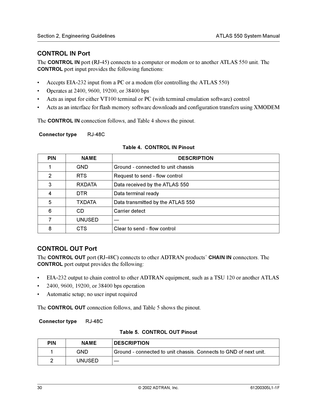
Control in Port
Connector type RJ-48C Control in Pinout
Connector type RJ-48C Control OUT Pinout
Control OUT Port
Alarm Relay Connector Pinout Name Description
Alarm Relay Connection
Connector type Usoc
Ethernet Connection
External Alarm Relay Monitor Connection
Shows the pinout for the External Alarm Relay connector
Network Interface Modules
T1/PRI Network Interface 15-pin Male D-connector Pinout
Test Interface
E1/PRA Network Interface 15-pin Female D-connector Pinout
Modem Management Network Module 6-pin Modular Jack Pinout
BRI Pinout
BRI DBU Network Module P/N 1200327L1
Option Module Interfaces
FXS Pinout
FXO Pinout
35 Winchester Pinout
Pin
DB-78 Connector Pinout
PIN Signal Description
EIA-530 Connector Pinout
System part number
EIA-530A Connector Pinout
RS-449/V.36 Connector Pinout
RS-232 Connector Pinout
Ccitt X.21/V.11 Connector Pinout
M Pinout
Trunk Circuit Connections
Trunk Circuit Connections for Various E&M Signaling Types
Quad BRI U-Interface Option Module P/N 1200315L1
T1/PRI Pinout
BRI Pinout S/T Interface
Quad BRI Isdn S/T Interface Option Module P/N 1200764L1
NxT1 Hssi Option Module P/N 1200346L1
Hssi SCSI-50 Connection Pinout PIN# + side PIN# side
Hssi SCSI-50 Connection Pinout
HSSI/V.35 Connection Pinout PIN# + side PIN# side
T1 Network Connection Pinout
Connector Types
HSSI/V.35 Connection Pinout
EIA-232 and V.35 Connection Pinouts
Octal Ethernet Switch Option Module P/N 1200766L1
Specifications Application Feature TDM Applications
AT-A-GLANCE Specifications
Lists the specifications for the Atlas 550 system
Switching Applications
Specifications Application Feature
IP Routing
Specifications Application Feature Voice Compression
Adpcm
Engineering Guidelines Atlas 550 System Manual
Grounding Instructions
Network Turnup Procedure
Unpack and Inspect the System
Mounting Options
Tools Required
Contents of Adtran Shipments
Introduction
Unpack and Inspect the System
Supplying Power to the Unit
AC Powered Systems
Grounding Instructions
DC Powered Systems
Installing Network and Option Modules
Mounting Options
Shipping Contents
Modem Management Network Module P/N 1200341L1
Dual Ussi Option Module System P/N 4200754Lx
Quad Basic Rate Isdn U-Interface Option Module P/N 1200315L1
Octal/Quad FXO Option Module P/N 1200310L1/1200329L1
Ethernet Switch Option Module P/N 1200766L1
Network Turnup Procedure Atlas 550 System Manual
User Interface Guide
Selecting the Appropriate Menu Security Levels
User Interface Guide Atlas 550 System Manual
Atlas 550 System Manual User Interface Guide
Navigating the Terminal Menu
Terminal Menu Window
Menu Path Left Pane
Alternate Menu View Window Pane Navigation
To do this Press this key
Navigating using the Keyboard Keys
Right Window Pane Notation
This notation Means that
Session Management Keystrokes
To do this
Selecting the Appropriate Menu
Set up the operational configuration for the Atlas
Terminal Menu and System Control
Review and monitor system status for the Atlas
Menu Descriptions
Password Security Levels
Security Levels
To do this Go to this menu
System Info
Displays the boot ROM revision
System Status
Displays the source of the event
Displays the port in which the event occurred
Displays a description of the event
Indicates the current status of the Ethernet port
Indicates whether the Ethernet network is 10 or 100BaseT
Normal condition
Failure condition
No Information Available
Configures the statistics displayed under data tables
User Interface Guide Atlas 550 System Manual
Performs reset daily at 1200 AM
Performs reset on Saturday night, 1200 AM
Display for collected resource usage data
Displays the usage data broken down by slots and ports
System Config
System Config Session Timeout
System Config Ethernet Port MAC Address
System Config Snmp Snmp Access
Specifies the IP address of the network manager
Defines Snmp managers characteristics as follows
Enables and disables Snmp trap transmission
Defines the destination for Snmp traps as follows
System Config Snmp Traps Destination Community
System Config Snmp DS1 Total Perf Thresholds
ESF
System Config Snmp DS1 Total Perf Thresholds Total ES Thrsh
System Config Snmp SNMP/ASP Proxy
System Config Snmp SNMP/ASP Polling
System Config Syslog Setup
License key
System Config Bonding Config Txfa Timer
System Config Alarm Relay Threshold
System Utility
System Utility Update Firmware Transfer Method
Indicates the slot number
Indicates the status of the current update
Indicates the time of the previous update
Defines the type of module for each slot
Indicates the current status of the transfer
Indicates the status of the previous transfer
Self-tests disrupt data flow
Displays which slot and port is currently being tested
Atlas 550 port number
Index number of the log
Atlas 550 slot number
Event description
Clears the self-test log
Specifies the IP address to ping
System Utility Ping Round Trip MAX
Displays status from current Telnet client sessions
System Utility Factory Default System
Modules
Modules Type
Modules T1/PRI-1 Info
Indicates a loss of signal detected on port interface
Displays the assembly revision of the module
Displays the current T1 alarm status
Receiving remote alarm RAI on port
Modules T1/PRI-1 DS0 Alarms
Modules T1/PRI-1 DS0 Status
Modules T1/PRI-1 SIG Status
Controlled Slip Second
Line Errored Second
Not be obtained
Unavailable Second
Modules T1/PRI-1 Configuration LBO
Displays the port number
Modules T1/PRI-1 Test PRT
Modules T1/PRI-1 Configuration Adlp Over FDL
Modules T1/PRI-1 Test
Modules T1/PRI-1 Test LOC LB
Modules T1/PRI-1 Test QRSS/RLB Results
Modules T1/PRI-1 Test Remote LB
Modules T1/PRI-1 Test Pattern
Modules T1/PRI-1 Test CLR
Modules E1/PRA-1 PRT
Displays the current E1 alarm status
Modules E1/PRA-1 Info
Displays the E1 framer hardware revision
Modules E1/PRA-1 Alarms
Modules E1/PRA-1 TS0 Alarms
Modules E1/PRA-1 TS0 Status
Modules E1/PRA-1 SIG Status
Modules E1/PRA-1 Configuration Nfas
Modules E1/PRA-1 Configuration TS16 MF
Modules E1/PRA-1 Configuration CRC-4
Modules E1/PRA-1 Test LOC LB
Modules E1/PRA-1 Test
Modules E1/PRA-1 Test PRT
Information
Modules E1/PRA-1 Test CLR
Modules E1/PRA-1 Test Pattern
Modules E1/PRA-1 Test Qrss Results
Modules E1/PRA-1 Test INJ
Displays the assembly revision
Displays the part number of the module
Displays the serial number of the module
Provides testing capabilities for the internal modem
Displays the results of the last Detect Dial Tone test
Indicates the current status of a particular Bonding session
Bonding
Modules DBU Bonding Configuration TXADD01 Timer
Near-end block errors
Far-end block errors
Displays the port number
Modules T1/PRI-2/4 Info
Modules T1/PRI-2/4 Info Part Number
Modules T1/PRI-2/4 Info PLL Status
Modules T1/PRI-2/4 Alarm Status
Modules T1/PRI-2/4 Alarm Status PRT
Modules T1/PRI-2/4 DS0 Status
Modules T1/PRI-2/4 DS0 Alarms
Modules T1/PRI-2/4 SIG Status
Modules T1/PRI-2/4 Performance 15MIN
Modules T1/PRI-2/4 Performance 24HR
Modules T1/PRI-2/4 Configuration LBO
Modules T1/PRI-2/4 Test PRT
Modules T1/PRI-2/4 Configuration Adlp Over FDL
Modules T1/PRI-2/4 Test
Modules T1/PRI-2/4 Test LOC LB
Modules T1/PRI-2/4 Test QRSS/RLB Results
Modules T1/PRI-2/4 Test Remote LB
Modules T1/PRI-2/4 Test Pattern
Modules T1/PRI-2/4 Test CLR
Modules V35NX-2 Info
Following signals are monitored these options are read-only
Modules V35NX-2 PLL/FIFO Port
Displays the Phase Lock Loop PLL and Fifo status
Modules V35NX-2 PLL/FIFO
Clears inband statistic results
Receive data Fifo full
Modules V35NX-2 PLL/FIFO PLL/FIFO
Receive data Fifo empty
Transmit data Fifo empty
Test
Follows Off
Modules V35NX-2 Dial PRT
Modules V35NX-2 Dial Mode
Modules V35NX-2 Dial
Modules V35NX-2 Dial Dial
Loopback toward the network
Modules V35NX-2 Test
Modules V35NX-2 Test 511 Result
Code
Modules V35NX-2 Test CLR
Modules USSI-2 Info
Modules USSI-2 DTE Status DTE Status
Modules USSI-2 Data Rate
Modules USSI-2 PLL/FIFO
Displays the data rate of the selected port
Provides information on the inband channel statistics
Modules USSI-2 PLL/FIFO Port
Modules USSI-2 PLL/FIFO PLL/FIFO
Modules USSI-2 Configuration CTS
Modules USSI-2 Dial PRT
Modules USSI-2 Dial Mode
Modules USSI-2 Dial
Modules USSI-2 Dial Dial
Modules USSI-2 Test Port
Modules USSI-2 Test 511 Result
Modules USSI-2 Test Inject
Modules USSI-2 Test CLR
Modules USSI-2 DTE Interface
Modules USSI-2 DTE Interface PRT
Detected with the endpoint or a cabling problem
Modules U-BRI-4 Alarms
Modules U-BRI-4 Alarms PRT
Modules U-BRI-4 Info
Modules U-BRI-4 Test
Modules U-BRI-4 Test PRT
Modules ST-BRI-4 Info
Modules ST-BRI-4 Alarms
Modules ST-BRI-4 Alarms PRT
Loops the entire physical interface
Modules ST-BRI-4 Alarms Alarms
Modules ST-BRI-4 Test
Modules ST-BRI-4 Test PRT
Option Module
Displays the processor ID of the selected module
Modules FXS-4/8 Info
Modules FXS-4/8 Status
Displays the status of each of the FXS ports
Modules FXS-4/8 Status PRT
Modules FXS-4/8 Status RX Abcd
Modules FXS-4/8 Test Port
Modules FXS-4/8 Status TX Abcd
Modules FXS-4/8 Test
Modules FXS-4/8 Test Test 2W
Modules FXS-4/8 Test TX Abcd
Modules FXS-4/8 Config
Modules FXS-4/8 Config PRT
Modules FXS-4/8 Test 1KHZ Tone
Modules FXS-4/8 Config RX Gain
Modules FXS-4/8 Config TX Gain
Modules FXO-4/8 Info
Modules FXO-4/8 Status
Modules FXO-4/8 Status PRT
Displays the status of each of the FXO ports
Modules FXO-4/8 Test
Modules FXO-4/8 Status RX Abcd
Modules FXO-4/8 Status TX Abcd
Modules FXO-4/8 Test Port
Modules FXO-4/8 Test TX Abcd
Modules FXO-4/8 Config
Modules FXO-4/8 Config PRT
Modules FXO-4/8 Test 1KHZ Tone
Modules FXO-4/8 Config RX Gain
Modules FXO-4/8 Config TX Gain
Modules E&M-8 Status
Modules E&M-8 Status PRT
Displays the status of each of the eight E&M ports
Modules E&M-8 Test
Modules E&M-8 Status RX Abcd
Modules E&M-8 Status TX Abcd
Modules E&M-8 Test Port
Modules E&M-8 Test 1KHZ Tone
Modules E&M-8 Config
Modules E&M-8 Config VF Ifce
Normal operation
Modules E&M-8 Config RX Gain
Data terminal ready from DTE
Modules LEGACY-4 Port Stats ERR FR
Modules NXT1 Hssi Info
Displays the firmware revision of the installed module
Modules Menu NXT1 Hssi and NXT1 HSSI/V.35 Option Modules
Modules NXT1HSSI T1 Menus
Indicates a loss of signal detected on the port interface
Modules NXT1HSSI Performance 15MIN
Modules NXT1HSSI Test
Modules NXT1HSSI Test Port
Modules NXT1HSSI Test LOC LB
Modules NXT1HSSI Imux Menus Status
Modules NXT1HSSI Imux Menus Config
Modules NXT1HSSI Imux Menus
Modules NXT1HSSI Imux Menus Status Port
Modules NXT1HSSI Hssi Menus
Modules NXT1HSSI Imux Menus Config Port
Modules NXT1HSSI Imux Menus Config GRP Assoc
Modules NXT1HSSI Hssi Menus Status
Hssi Interface Loopback Test Diagram
Following loopback status messages may display
Modules NXT1HSSI Hssi Menus Status LC
Modules NXT1HSSI Hssi Menus Status CA
Modules NXT1HSSI Hssi Menus Status LA and LB
Modules NXT1HSSI Hssi Menus Status TA
Modules NXT1HSSI Hssi Menus Config TX CLK
Modules NXT1HSSI Hssi Menus Config
Modules NXT1HSSI Hssi Menus Config Port Name
Modules NXT1HSSI Hssi Menus Config CTS
Modules NXT1HSSI Hssi Menus Test
Modules NXT1HSSI Hssi Menus Config DCD
Modules NXT1HSSI Hssi Menus Config CA
Modules NXT1HSSI Hssi Menus Test Port
Modules ENET-8 Status
Modules NXT1HSSI Hssi Menus Test Remote Lpbk Hssi
Modules ENET-8 Info
Modules ENET-8 Status Port
Modules VCOM-X Info
This resource is currently changing state
This resource was reinitialized after excessive errors
Principle applies to the VCOM-8, 24, and 32 Option Modules
This resource is currently in use
Ccitt G.723.1 compression 6.3 kbps bandwidth
Proprietary Netcoder compression 6.4 kbps bandwidth
Voice status until the FAX protocol is established
Is between protocol states
Dual-tone, multi-frequency Dtmf digit received
Session
Marking a device as Disabled prevents the Atlas 550 from
Any calls routed to it
Modules VCOM-X Statistics Atlas Frms
Modules VCOM-X Statistics Atlas Drop
Modules ADPCM-32 Info
Modules ADPCM-32 Status Status
Modules ADPCM-32 Status
Modules ADPCM-32 Status Device
Displays the status of each of the packet voice resources
Modules ADPCM-32 Config
Modules ADPCM-32 Config Configure ADPCM-32 Devices
Modules ADPCM-32 Statistics Atlas Frms
Modules ADPCM-32 Statistics Atlas Drop
Modules ADPCM-32 Statistics ADPCM-32 Frms
Modules ADPCM-32 Statistics ADPCM-32 Drop
Modules Bonding Status
Displays the board revision of the installed module
Modules Bonding Info
Displays the current status of the Bonding session
Modules Bonding Status Bonded EP
Modules Bonding Configuration Txdeq Timer SEC
Packet Manager
Signaling using Ansi T1.617-D
Interface NNI mode
Signaling using ITU-T Q.933-A
Signaling using Group of Four
Is waiting for an acknowledge
Sent configuration request
Enabled, occurs now
But the peer has not acknowledged us
Endpoint on all PVCs
Violations
Clears all values in this submenu
Displays the current state of the LCP negotiations
Resets the Tx and Rx packet counters
Clears all values in this submenu
Number of packets transmitted over this link
Resets all sublink counters
Local address for each PVC as assigned by the carrier
Total number of Fecn bits received on this PVC
Creates and configures packet endpoints
Total number of Becn bits received on this PVC
For Adtran internal use only
Acts as the network side of the UNI interface
Remote device does not support frame relay signaling
Operates in NNI mode
Acts as the user side of the UNI interface
Displays the configuration for this packet endpoint
Contains the Authentication parameters for this endpoint
This turns on authentication debugging
Username that the peer will use to authenticate the Atlas
Password that the peer will use to authenticate the Atlas
This turns on LCP negotiation debugging
Packet Manager Packet Endpnts Config Config Sdlc
User-definable name for the Dlci
Tate to a UTO for normal operation
Allows configuration of parameters for each Dlci
This Dlci disregards the status as reported from the switch
Reports Active to all packet endpoints within Atlas
Diagnostic Mode
Disables backup switching
Provides switching options
Forces a switch to backup
Provides normal operation
Displays the name of the packet endpoint
Displays the protocol running on the packet endpoint
Displays the user-defined name for the Dlci
Displays the test mode for the PVC
Shows the duration in seconds for the fixed-duration test
Displays the average round trip delay for the current test
Resets the counters
Displays the total number of packet endpoints configured
Indicates data source
Indicates data destination
Displays the port number and name
Indicates collection of IQ data for the target Dlci
Within the given link
Displays the Data Link Connection Identifier circuit number
Sets the parameters for IQ statistics gathering
Number of frames the port received for the interval or day
Number of bytes the port received for the interval or day
Time, in seconds, the signaling state has been down
Number of PVC-signaling, full-status frames received
Number of PVC-signaling, full-status frames transmitted
Number of frames discarded by the IQ unit
Number of frames received with CRC errors
Number of single PVC status frames received
Number of frames received without proper flag termination
Packet Manager Frame Relay IQ View IQ Statistics Sublink
Number of DEs the PVC has received for the interval or day
Number of CRs the PVC has received for the interval or day
Maximum frame size the PVC received for the interval or day
Number of lost frames on the PVC for the interval or day
Minimum frame size the PVC received for the interval or day
Average frame size the PVC received for the interval or day
Number of state changes for this PVC for the interval or day
Router
Router IP ARP Cache MAC Address
Router IP ARP Cache
Router IP ARP Cache IP Address
Adds a static route to the router
Router IP ARP Cache Time
Router IP ARP Cache Type
Clears the Used menu and resets the value to zero
Router IP Routes TTL
Dlci Number
Route table
Route address see the following, Far-End Address
This virtual circuit
On this virtual circuit
Are listened to
No modification of the routing metric
RIP advertisements are periodically transmitted
Defines when RIP advertisements are transmitted
Defines the secret used to advertise routes when using RIP
Learned routes do not age
Router IP Ping
Specifies the number of pings to send. The maximum value is
Ctrl + \ Ctrl + Shift +
Transport layer protocol
Received in error
Host
Destination address was not a local address
550, and the Source-Route option processing was successful
IP Statistics Name Description
Number of Icmp Parameter Problem messages sent
Having errors bad Icmp checksums, bad length, etc
Number of Icmp Parameter Problem messages received
Clears the accumulated statistics
Number of Icmp Timestamp request messages sent
Number of Icmp Echo request messages sent
Number of Icmp Echo Reply messages sent
Number of Icmp Timestamp Reply messages sent
Total number of UDP datagrams delivered to UDP users
Established or CLOSE-WAIT
Excluding those containing only retransmitted octets
Destination port
Router IP UDP Relay
Router IP UDP Relay Enable
Enables/disables the router to act as a relay agent
Specifies the UDP port 1 to 65,535 in the UDP Port columns
Dedicated Maps
Displays the index number of the available maps
Dedicated Maps CREATE/EDIT Maps Connects Port
Specifies which days of the week the map is active
T1 Trunk Conditioning Service
TS0 Rate
Defines ports to be used for this connection
Answer Supervision
Rx AB Tx AB
Dedicated Maps FXO CREATE/EDIT Maps Connects TO/FROM Config
Sets the DS0 rate to either 56 or 64 kbps
Dedicated Maps Ussi CREATE/EDIT Maps Connects TO/FROM Config
Dedicated Maps NXT1 Hssi and NXT1 HSSI/V.35 Modules
DS0S Available
Configures the port to use Flags or Ones as the idle code
Legacy Data Option Module
Receive Idle Code
Voice Port
This activator forces a link in/out of backup
Circuit Status Menu
Link is in error and waiting on backup
Attempting to dial the backup link
Will retry backup dialing in num seconds
Link is answering a backup endpoint
No current test call on this dedicated dial backup circuit
Passed last manual or scheduled test
Failed last manual or scheduled test
Dial Plan
Dial Plan Network Term PORT/PEP
Dial Plan Network Term OUT#ACCEPT Accept Number
Dial Plan Network Term OUT#ACCEPT Treat Call AS
Dial Plan Network Term Subst Templ ORIGINAL#
Equipment. In this case, Atlas 550 is acting as the network
Dial Plan User Term IN#ACCEPT SRC ID
Primary accept number for the local exchange would be N$,
IXC trunks are unavailable busy or in alarm. In this case,
Primary endpoints are unavailable
Secondary accept would be 1$
Dial Plan User Term Ifce Config
Dial Plan User Term Subst Templ
Local area code. Use for sending caller ID to the network
Use extreme caution when forcing Collision Response
Specifies the configuration parameters for the endpoint
AT&T 4ESS
Dial Plan T1/PRI Network Term PRI Ifce Config PRI Strip MSD
Switched Digital Network
AT&T SDN
Contiguous channels from last to first
Dial Plan T1/PRI Network Term RBS
Would be used if available
Send a progress message to the CPE and map busy tones
From the network
Dial Plan T1/PRI Network Term RBS Ifce Config RBS
Dial Plan T1/PRI Network Term RBS Ifce Config RBS First DS0
Loop Start
Dial Plan T1/PRI Network Term RBS Ifce Config RBS did Digits
ANI/DNIS
Dial Plan T1/PRI Network Term RBS Ifce Config RBS Strip MSD
Dial Plan T1/PRI Network Term RBS Ifce Config RBS Source ID
Must define the trunk number
272 ADTRAN, Inc
Among the available DS0s on this interface
Dial Plan T1/PRI User Term PRI
Would be used if available
Received
Dial Plan T1/PRI User Term PRI Ifce Config PRI Strip MSD
Dial Plan T1/PRI User Term PRI Ifce Config PRI Swap ANI/DNIS
Dial Plan T1/PRI User Term RBS Ifce Config RBS
Dial Plan T1/PRI User Term RBS Ifce Config RBS First DS0
Dial Plan T1/PRI User Term RBS
61200305L1-1F ADTRAN, Inc 277
Dial Plan T1/PRI User Term RBS Ifce Config RBS Strip MSD
Dial Plan T1/PRI User Term RBS Ifce Config RBS Source ID
Through this endpoint. This item is optional
Dial on Offhook number must be specific i.e., no wildcards
Dial Plan T1/PRI User Term RBS Ifce Config RBS DS0 Selection
Dial Plan E1/PRA Network Term PRA Ifce Config PRA First DS0
Dial Plan E1/PRA Network Term PRA Ifce Config PRA Source ID
Dial Plan E1/PRA User Term PRA
Dial Plan E1/PRA User Term PRA Ifce Config PRA Swap ANI/DNIS
Phone numbers assigned to this BRI phone line
Spid Number
Dial Plan U-BRI User Term
Dial Plan U-BRI User Term Ifce Config Strip MSD
From the Network Pstn
Caller ID number must be specific i.e., no wild cards
Available
Contiguous ports from last to first
Dial Plan FXS User Term Ifce Config ANI to Caller ID
Dial Plan FXO Network Term Ifce Config Number of Ports
Dial Plan FXO Network Term Ifce Config Strip MSD
DPT
Dial Plan FXO User Term Ifce Config Direct Inward Dialing
Dial Plan Octal E&M Module Dial Plan E&M User Term
Dial Plan E&M User Term Ifce Config Signaling Method
Dial Plan E&M User Term Ifce Config Source ID
Specifies the number to dial on an outgoing call
Dial Plan V35NX User Term Ifce Config Source ID
Dial Plan Ussi User Term Ifce Config Ports Available
Dial Plan Ussi User Term Ifce Config MIN DS0’S
Selects the time delay in seconds between redial attempts
For User terminations, the number of calls is fixed at
Defines the number dialed to originate a call
Defines the number of redials to attempt
Dial Plan PKT Endpt User Term Ifce Config Call Party Number
Backup
Endpoint will originate the backup call
Backup if an error is detected
This only applies to originating endpoints
RED, Yellow, or Blue alarms
When network is out of alarm
Only by the Manual activator
This is the time of day to enable dial backup
How often test calls are to be made
Date of the next scheduled test call
Selects the appropriate Dlci for this dial plan entry
Dial Plan PKT Voice Network Term Ifce Config did Prefix
Dial Plan PKT Voice Network Term Ifce Config Strip MSD
Dial Plan PKT Voice User Term Ifce Config Conflict Report
Dial Plan PKT Voice User Term Ifce Config Strip MSD
Detail Level Procedures
DLP-Index Atlas 550 System Manual
Connecting the Terminal or PC to the CONTROL/CRAFT Port
Introduction
DLP-001
Perform Steps Below in the Order Listed
Logging in to the System
DLP-002
61200305L1-1F ADTRAN, Inc 321
322 ADTRAN, Inc
Setting IP Parameters for the Atlas
Enter the appropriate Default Gateway
Enter the appropriate IP address
Enter the appropriate Subnet Mask
Access to a PC or other computer connected to the LAN
Verifying Communications Over AN IP LAN
DLP-004
Atlas 550 System Manual DLP-004 Telnet to the Atlas
328 ADTRAN, Inc
ADDING/REMOVING Users and Changing Password Security Levels
VT100 terminal or PC with VT100 terminal emulation software
DLP-005
Select level... If you want the user to
Updating the Firmware Using Tftp
DLP-006
Atlas 550 System Manual DLP-006
334 ADTRAN, Inc
Updating the Firmware Using Xmodem
DLP-007
Atlas 550 System Manual DLP-007
338 ADTRAN, Inc
Saving the Current Configuration Using Tftp
DLP-008
Respond with Y to confirm request
Loading a Configuration Using Tftp
DLP-009
Respond with Y to confirmation request
Saving the Current Configuration Using Xmodem
DLP-010
Loading a Configuration Using Xmodem
Review the steps above for possible configuration errors
DLP-011
Connecting the Atlas 550 to AN External Modem
DLP-012
Atlas 550 System Manual DLP-012
350 ADTRAN, Inc
Using the Adtran Utility Syslog with the Atlas
Setting Up the Atlas 550 to use the Syslog
Setting Up the Syslog Host
Additional Syslog Features
354 ADTRAN, Inc
Connecting the Alarm Contacts
Alarm Relay Connector Pinout
DLP-014
Atlas 550 System Manual DLP-014
358 ADTRAN, Inc
Using the Alarm Connections and ACO Button
DLP-015
Perform the Steps Below in the Order Listed
Clearing the Alarm Relay Remotely
362 ADTRAN, Inc
Configuration Guides
CFG-6 Atlas 550 System Manual
Dial Backup for Dedicated T1 Circuits
Before You Begin
Configuring the Dedicated T1 Data Link
CFG-001
61200305L1-1F ADTRAN, Inc 367
368 ADTRAN, Inc
Configuring the Dial Backup PRI
370 ADTRAN, Inc
61200305L1-1F ADTRAN, Inc 371
Configuring the Dial Backup Endpoint
SLT field in the Dedicated MAP
ORIGINATE/ANSWER
MIN DS0S
376 ADTRAN, Inc
System Event Logging
Setting the Event LOG Category
Atlas 550 System Manual System Event Logging
Viewing the Events
System Events
System Controller Events Console Log String Category
Console Log String Category Event
Switchboard Events Console Log String Category
System Controller Events
Nx 56/64 Events Console Log String Category
Nx 56/64 Events
T1 Events Console Log String Category
T1 Events
Ethernet Events
Isdn Events
Circuit Backup Events
Modem Management Module Events Console Log String Category
DP Outgoing Signaling Events
Isdn Cause Codes
Isdn Cause Code Events Category
Incompatibledest Major Interworkingunspec
Code Location
Cause Code LOG Entries
Cause Code Log Entry Location Designations
Isdn Layer 2 Lapd Message
390 ADTRAN, Inc
VT100 Utility
Adtran Utilities
Telnet Utility
Tftp Server
Telnet Utility
Telnet Menu Tree
Click on Session to open the Telnet session
Establishes the Telnet session
Connect
Provides viewing alternatives for the terminal screen
Provides Copy and Paste commands
Ends the Telnet session and closes the Telnet screen
Echoes each character that you enter
Opens the on-line help
Provides on-line help for using the Adtran Utilities
VT100 Utility
Displays version and owner information
Uploads and downloads files to and from an Atlas
Opens VT100 terminal emulation session
Opens a specified serial port for a VT100 session
Selects the Xmodem file transfer protocol
Redraws the screen
Provides terminal screen commands
Identical to the Telnet Edit Menu see Edit Menu on
Identical to Telnet Colors Menu see Colors on
Tftp Server
Tftp Server Interface Menu Tree
Terminates active transfers and closes the Tftp window
Provides enable, disable, abort, and exit options
Terminates a transfer that is in progress
Provides print options
Log Field
Xmit meter provides a visual record of the transfer process
MIB
MIBs Supported by the Atlas
MIB Compilation Order
Traps Supported by the Atlas
404 ADTRAN, Inc
61200305L1-1F ADTRAN, Inc 405
MIB Variables Supported by the Atlas
IpInAddrErrors
IpDefaultTTL
IpInHdrErrors
IpForwarding
IpForwDatagrams
IpReasmTimeout
IcmpInErrors
IpInUnknownProtos
IcmpInRedirects
IcmpInSrcQuenchs
IcmpOutErrors
IcmpInEchos
TcpAttemptFails
TcpEstabResets
TcpInSegs
TcpCurrEstab
61200305L1-1F ADTRAN, Inc 411
Rfc1406.mib 6.1.2.1.10.18
61200305L1-1F ADTRAN, Inc 413
Rfc1315.mib 6.1.2.1.10.32
Adtran.mib 6.1.4.1.664
Ads1.mib 6.1.4.1.664.2.3
Atunit.mib 6.1.4.1.664.2.154.1.5
Atmod.mib 6.1.4.1.664.2.154.1.6
Atv35nx.mib 6.1.4.1.664.2.154.1.7
Atbri.mib 6.1.4.1.664.2.154.1.8
Att1.mib 6.1.4.1.664.2.154.1.9
61200305L1-1F ADTRAN, Inc 421
Atvoice.mib 6.1.4.1.664.2.154.1.10
Athssv35.mib 6.1.4.1.664.2.154.1.11
At550.mib 6.1.4.1.664.2.219
Atqbriu.mib 6.1.4.1.664.2.274
Fperform.mib 6.1.4.1.664.4.1
61200305L1-1F ADTRAN, Inc 425
426 ADTRAN, Inc
61200305L1-1F ADTRAN, Inc 427
428 ADTRAN, Inc
61200305L1-1F ADTRAN, Inc 429
430 ADTRAN, Inc