Americas Headquarters
Text Part Number OL-23091-01
Page
N T E N T S
Iii
Manager
Editing Values
Telephony Features Available for the Cisco Unified IP Phone
Network Configuration
Vii
Verifying Dhcp Settings
Viii
Technical Specifications D-1
OL-23091-01
Overview
Audience
Organization
Chapter Description
Cisco Unified Communications Manager Administration
Related Documentation
Cisco Unified IP Phone 7900 Series
Cisco Unified Communications Manager Business Edition
Document Conventions
Cisco Product Security Overview
Convention Description
Boldface font
Xiv
An Overview of the Cisco Unified IP Phones
Cisco Unified IP Phone 7962G
Cisco Unified IP Phone 7942G
Cisco Unified IP Phone 7941G and 7941G-GE
What Networking Protocols are Used?
Networking Protocol Purpose Usage Notes
CDP
Cppdp
Dhcp
Cisco Tftp in the Cisco Unified Communications
Manager Features and Services Guide
See Network Configuration Menu,
IPv6 in the Cisco Unified Communications
See the LLDP-MED and Cisco Discovery Protocol
IPv6 Support on Cisco Unified IP Phones
Communications Manager Security Guide
Unified Communications Manager System Guide
Related Topics
Feature Overview
Configuring Telephony Features
Providing Users with Feature Information
Related Topic
See Troubleshooting Guide for Cisco Unified
Topic Reference
Communications Manager
Overview of Supported Security Features
Feature Description
Feature Description
More information, see Device Configuration Menu,
Understanding Security Profiles
More information
Establishing and Identifying Secure Conference Calls
Establishing and Identifying Protected Calls
Call Security Interactions and Restrictions
Security Restrictions with Conference Calls
Supporting 802.1X Authentication on Cisco Unified IP Phones
Overview
Required Network Components
Best Practices-Requirements and Recommendations
Reducing Power Consumption on the Phones
Security Restrictions
OL-23091-01
Purpose For More Information
Communications Manager Administration
See Cisco Communications Manager
Guide
Installing Cisco Unified IP Phones
Checklist for Installing the Cisco Unified IP Phones
Administration Guide
Task Purpose For More Information
See Providing Power to the Cisco Unified IP
See Installing the Cisco Unified IP Phones
See Feature Key Capacity Increase for Cisco
Phones,
See Configuring Startup Network Settings
Network Configuration IPv4 Configuration and configure
Choose Settings Network Configuration IPv4
Choosing Settings Network Configuration
Network Configuration IPv6 Configuration and configure
Network Configuration IPv6 Configuration
See Cisco Unified IP Phone 7962G, 7942G
7961G, 7961G-GE, 7941G, and 7941G-GE
A P T E R
Related Topic
Providing Power to the Cisco Unified IP Phones
Power Guidelines
Power Outage
Power Type Guidelines
Understanding Phone Configuration Files
Obtaining Additional Information about Power
Understanding Phone Configuration Files
Resolving Startup Problems,
Security Guide, Configuring the Cisco CTL Client
Understanding the Phone Startup Process
Purpose Related Topics
Security Guide, Security by Default
Adding Phones with Auto-Registration,
Adding Phones with Auto-Registration
Requires
Method Address?
Adding Phones with Auto-Registration and Taps
Procedure
Adding Phones with BAT
Using Cisco Unified IP Phones with Different Protocols
See Configuring Startup Network Settings,
Converting a New Phone from Sccp to SIP
Converting an In-Use Phone from One Protocol to the Other
Deploying a Phone in an Sccp and SIP Environment
OL-23091-01
Setting Up the Cisco Unified IP Phones
Before You Begin
Cisco Unified Communications Manager Configuration
Network and Access Ports, Handset, Speakerphone, Headset,
Understanding the Cisco Unified IP Phone Components
Network Requirements
Network and Access Ports
Handset
Connecting a Headset
Speakerphone
Headset
Audio Quality
Enabling a Wireless Headset on the Cisco Unified IP Phones
Using External Devices
Disabling a Headset
Installing the Cisco Unified IP Phones
Before You Begin
See Adding Phones to the Cisco Unified Communications
Adapter port
See Network and Access Ports, page 3-3for guidelines
Connect a straight-through Ethernet cable from
Cisco Unified IP Phone 7962G and 7942G Cable Connections
Attaching a Cisco Unified IP Phone Expansion Module
Feature Key Capacity Increase for Cisco Unified IP Phones
Click Apply Config
Apply Configuration Information dialog appears
Adjusting the Placement of the Cisco Unified IP Phone
Adjusting Cisco Unified IP Phone Placement on the Desktop
Configuring Softkey Templates,
Securing the Phone with a Cable Lock
Mounting the Phone to the Wall
Parts Used in Wall Mounting the Cisco Unified IP Phone
Verifying the Phone Startup Process
Configuring Startup Network Settings
Configuring Security on the Cisco Unified IP Phones
From the phone, choose Settings Security Configuration
Related Topic
Configuring Settings on the Cisco Unified IP Phones
Configuration Menus on the Cisco Unified IP Phones
Displaying a Configuration Menu
Unlocking and Locking Options
Editing Values
Overview of Options Configurable from a Phone
IPv4 Network Settings
Category Description
PC Vlan
Network Configuration Menu
IPv6 Network Settings
Option Description To Change
Option Description To Change
Configuration
System Enterprise Phone
Unified CM, the data
Cannot be changed on
VPN
OL-23091-01
Option Description To Change
Cisco Unified Communications Manager Security
Guide. For information about unlocking CTL
ITL files, see Unlocking the CTL and ITL Files
Configuration menu. a new
From the new Tftp Server
4describes the IPv6 configuration menu options
Option Description To Change
Yes
Unified Communications Manager Security Guide. For
Information about unlocking the CTL file, see Unlocking
CTL and ITL Files,
Understanding DHCPv6 and Autoconfiguration
Device Configuration Menu
Unified CM Configuration Menu
Configuration in the Cisco Unified Communications Manager
State
Designation Description
SIP Configuration Menu for SIP Phones Only
SIP General Configuration Menu
Device Settings SIP Profile
See Cisco Unified Communications Manager Security Guide
Line Settings Menu for SIP Phones
Displaying a Configuration Menu, Device Configuration Menu,
Call Preferences Menu for SIP Phones
Http Configuration Menu
Routing Directory Number
Device Phone Add a New Speed Dial
Locale Configuration Menu
Is activated
NTP Configuration Menu for SIP Phones
NTP Configuration Menu for SIP Phones
Reference
UI Configuration Menu
Device Phone Phone Configuration
Phone Configuration
Parameters
Gets used see Media Configuration Menu
User Preferences Audio Preferences Wideband Handset
User Preferences Audio Preferences Wideband Headset
Media Configuration Menu
That the remote party receives. The remote party
Is the party who is on a call with the party whose
See also Recording Tone
Phone Configuration to set this value
User
Preferences Audio Preferences
Wideband Handset
Ethernet Configuration Menu
For more information, see the Cisco Unified
Communications Manager System Guide, Cisco
Security Configuration Menu
Web Page Access,
QoS Configuration Menu
Displaying a Configuration Menu, Network Configuration Menu,
Network Configuration Menu
Call Statistics Screen, Streaming Statistics,
Option Description To Change
Protocol. Settings include Enabled-default Disabled
Settings Common Device Configuration
See Table
Security Configuration Menu
MIC
Proxy Function in Cisco Unified Communications
LSC
System Administration Guide, Security
CTL File Submenu
Cisco Unified Communications Operating
Cisco Unified Communications Manager
ITL file, see Security by Default
ITL File Submenu
Unlocking the CTL and ITL Files
Cisco Unified Communications
Unified Communications Manager
Security Guide
Cisco Unified
Communications Operating
System Administrator Guide
Configuring the Cisco CTL Client in Cisco Unified
Trust List Menu
Capf server used by the phone. Also displays
802.1X Authentication and Status
Authentication
Trusted Srst router that is available to
Choose Settings Security Configuration
802.1X Authentication Device
802.1X Authentication EAP-MD5
EAP-MD5
VPN Configuration
Connecting to VPN
25describes the 802.1X Authentication Real-Time Status
When the power is lost
VPN Configuration Settings
Choose Settings Security
Configuration VPN Configuration
Concentrator 1, Concentrator 2, or
Concentrator 3, as desired
AES128-SHA
AES256-SHA DES-CBC3-SHA
Configuring Features, Templates, Services, and Users
Feature Description Configuration Reference
Administration Guide, Cisco Unified IP
Features and Services Guide, Barge
Choose System Service Parameter and select
Administration Guide, SIP Profile
Communications Manager Features
Services Guide, Call Pickup
Amwi
Configuration System Enterprise Phone
Services Guide, External Call Transfer
Restrictions
Services Guide, Presence
Communications Manager Feature
Features and Services Guide, Call Back
Features and Services Guide, Call Display
Forward Maximum Hop Count service parameter
Communications Manager System Guide
During a call when it is being recorded
Services Guide, Monitoring and Recording
Identification enabled
Incoming call information on the phone screen
Communications Features and Services
Unified Communications Manager Features
Services Guide, Cisco IP Manager
CMC
Guide, CTI Route Point Configuration
Services Guide, Custom Phone Rings
System Guide, Conference Bridges
Services Guide, Do Not Disturb
Phone Services Configuration
Services
System Guide, Cisco Unified IP Phone
Unified Communications Manager Features
Feature, see Cisco Unified Communications
Manager Features and Services Guide, Hold
Administration Guide, Hunt List
Administration Guide, CTI Route Point
Feature and Services Guide, Intercom
See Cisco Unified Communications
Manager System Guide, Cisco Unified IP
Features and Services Guide, Malicious
Administration Guide, Message Waiting
Cisco Communications Manager System
Services Guide, Music On Hold
Mlpp
Plar
Features and Services Guide Barge
Administration Guide, Phone Button
Administration Guide, Modifying Phone
Features and Services Guide, Quality
Features and Services Guide, Custom
Phone Rings
Creating Custom Phone Rings,
Administration Device Phone
Manager Administration System
Administration Guide, Conference Bridge
Unified Communications Manager
Features and Services Guide, Cisco Unified
Mobility and Cisco Unified Mobility
Advantage and Cisco Unified Mobile
Communicator Integration
Administration Guide, Device Pool
On the call. The user might hear a monitoring
Configuration Layout pane and select
Settings Common Phone Profile,
Administration Guide, Time Period
Manager Administration Guide
Configuring Product Specific Configuration Parameters
Cisco VT Advantage Administration
Administration Guide, Cisco Voice-Mail
Configuration Window Path Parameters
Device Device Settings
Common Phone Profile
Device Phone Product
Configuring Corporate and Personal Directories
Configuring Corporate Directories
Configuring Personal Directory
Modifying Phone Button Templates
Cisco Unified IP Phone 7962G
Cisco Unified IP Phone 7942G
Cisco Unified IP Phone 7961G /7961G-GE
Choose Device Device Settings Phone Services
Find and List IP Phone Services window displays
Configuring Softkey Templates
Setting Up Services
Adding Users to Cisco Unified Communications Manager
Giving Users Access to the User Options Web Pages
Managing the User Options Web Pages
Click Add Selected
Specifying Options that Appear on the User Options Web Pages
Click Device Association
Enabling EnergyWise on the Cisco Unified IP Phone
Field Description
Field Description
Setting up UCR
Configuring UCR 2008 in Phone
Choose Device Phone
Configuring UCR 2008 in Common Phone Profile
Configuring UCR 2008 in Enterprise Phone Configuration
Set the Https Service parameter to https only
Choose Device Device Settings Common Phone Profile
OL-23091-01
Customizing and Modifying Configuration Files
Customizing the Cisco Unified IP Phones
Creating Custom Phone Rings
Ringlist.xml File Format Requirements
Configuring a Custom Phone Ring
Creating Custom Background Images
PCM File Requirements for Custom Ring Types
List.xml File Format Requirements
List.xml Example
Configuring a Custom Background Image
PNG File Requirements for Custom Background Images
Configuring Wideband Codec
Monitoring the Cisco Unified IP Phones Remotely
Accessing the Web Page for a Phone
Disabling and Enabling Web Page Access
Click Update
Device Information
Phone. -1describes these items
UDI
Network Configuration
Templates, Services, and Users
Description
Cannot be changed on the phone
Vlan
PC Vlan
Network Statistics
OL-23091-01
Device Logs
Streaming Statistics
Stream 1 and Stream
Stream 4, or the Stream 5 hyperlink
MOS LQK
Information, see Monitoring the Voice Quality of Calls,
Cisco Unified IP Phone uses
Voice Quality Metrics
Uses
Related Topics
A P T E R
For your phone, see Using the Certificate Authority
See Using Cisco Unified IP Phones with Different
Model Information Screen
Status Menu
Status Messages Screen
Select Status Messages
Message Description Possible Explanation and Action
Address. See Network Configuration Menu
Configuration 802.1X Authentication option on
Authentication and Status,
Unified Communications Manager Security Guide
Network Configuration Menu, page 4-5section
If you are using DHCP, check the Dhcp server
Configuration Menu, page 4-34for details
Menu, page 4-5for details
See Firmware Versions Screen, page 8-12to verify
Device Phone
Configuration Menu, page 4-5for details
Provided a DNS server. Check the Dhcp server
See Cisco Unified Communications Manager Security
Message Description Possible Explanation and Action
Network Statistics Screen
Select Status Network Statistics
Port
IPv4
Firmware Versions Screen
IPv6
Select Firmware Versions
To exit the Firmware Version screen, press the Exit softkey
Expansion Module Status Screen
Select Expansion Module
To exit the Expansion Module screen, press the Exit softkey
Press the Settings button Select Status
Call Statistics Screen
Select Call Statistics
Preceding 8-second interval of the voice stream. For more
That the Cisco Unified IP Phone uses
Using Test Tone
Place a call
Status Menu
Troubleshooting and Maintenance
Resolving Startup Problems
Identifying Error Messages, Checking Network Connectivity,
Identifying Error Messages
Verifying Tftp Server Settings
Checking Network Connectivity
Verifying IP Addressing and Routing
Verifying DNS Settings
Verifying Cisco Unified Communications Manager Settings
Cisco CallManager and Tftp Services Are Not Running
Choose Tools Control Center Feature Services
Creating a New Configuration File
Be removed from the phone and deleted if necessary
Cisco Unified IP Phone Resets Unexpectedly
Symptom Cisco Unified IP Phone Unable to Obtain IP Address
Verifying the Physical Connection
Verifying Dhcp Settings
Checking Static IP Address Settings
Verifying the Voice Vlan Configuration
Verifying that the Phones Have Not Been Intentionally Reset
Eliminating DNS or Other Connectivity Errors
Checking Power Connection
Troubleshooting Cisco Unified IP Phone Security
Problem Possible Cause
General Troubleshooting Tips
Explanation
Unlocking and Locking Options, page 4-2for details
To resolve this problem, re-enable the port from the switch
Summary Explanation
Halfduxcollisionexceedthreshold
OL-23091-01
Resetting or Restoring the Cisco Unified IP Phones
Performing a Basic Reset
Problem Solution
Press the Services, Settings, or Directories
Performing a Factory Reset
Options see Unlocking and Locking Options
Locking Options, page 4-2. Then press
Using the Quality Report Tool
Monitoring the Voice Quality of Calls
Using Voice Quality Metrics
Where to Go for More Troubleshooting Information
Troubleshooting Tips
Metric Change Condition
Cleaning the Cisco Unified IP Phone
Giving Users Access to the User Options Web Pages
Providing Information to Users Via a Website
How Users Get Copies of Cisco Unified IP Phone Manuals
How Users Access a Voice Messaging System
How Users Subscribe to Services and Configure Phone Features
How Users Configure Personal Directory Entries
Installing the Synchronizer
Ready to Install window displays
Configuring the Synchronizer
Programs Cisco Systems TabSync
OL-23091-01
Feature Support by Protocol for Cisco Unified IP Phone
Features
MWI
Manager
FAC
Tool
Cisco Unified IP Phone Service Application
SDK Compliance Supported
Development Notes
Cisco Unified Communications Manager Features
Services Guide
Cisco Unified Communications Manager Assistant
Cisco Unified IP Phone Expansion Module
Supporting International Users
Adding Language Overlays to Phone Buttons
Support for International Call Logging
Physical and Operating Environment Specifications
Specification Value or Range
100-240 VAC, 50-60 Hz, 0.5 A-when using the AC adapter
Cisco Unified IP Phone 7962G and 7942G
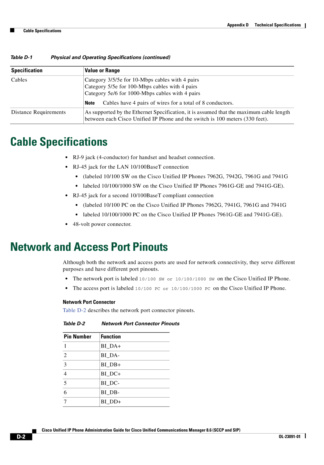
Cable Specifications
Network and Access Port Pinouts
Network Port Connector
Pin Number
Access Port Connector
Pin Number Function
OL-23091-01
Basic Phone Administration Steps
Example User Information for these Procedures
Proceed to Configuring the Phone, page E-3
Adding a User From an External Ldap Directory
Choose System Ldap Ldap Directory
Click Perform Full Sync Now
Configuring the Phone
Proceed to the section Configuring the Phone, page E-3
Example johndoe
Example doe
Procedure
OL-23091-01
Choose User Management End User
Click Device Associations
Performing Final End User Configuration Steps
IN-1
PNG file
Capf Certificate Authority Proxy Function
IN-2
Conference joining Configurable call forward display
Client matter codes
PCM file requirements
IN-3
Fast dial B-3
IN-4
Hold status Ihold Hold reversion
Hunt groups
IN-5
Immediate Divert enhanced feature
IN-6
Host Name IPv4 Alternate Tftp Bootp Server Default Router
IN-7
CDP Cppdp Dhcp Http Rtcp RTP Sccp SIP TCP Tftp TLS UDP
Lldp
IN-8
Dscp For Configuration
IN-9
Description Establishing Identifying Restrictions
IN-10
IN-11
Mobile connect TLS Mobile voice access Transfer
Trivial File Transfer Protocol
Secure and nonsecure indication tone
DNS
Accessing Debug Display
Disabling access to Ethernet Information
IN-13
Stream
IN-14
IN-15