System Board Assembly
The system board assembly contains the DIMMs, Pentium II or Pentium III processor/heat sink, Processor Power Module(s), system board with tray, the AGP Graphics Controller, and the external battery, if installed. Each of these components is spared separately. The components on the system board are illustrated in Figure
CAUTION: Static electricity can damage the electronic components of the workstation. Before beginning these procedures, make sure you are properly grounded. See “Electrostatic Discharge Information” in Chapter 2.
System Board with Tray and Cage
To remove the system board with tray and cage:
1.Perform the service preparations shown on page
2.Remove the following components:
❏Workstation feet
❏Side access panel
❏I/O bracket assembly
3.Disconnect and remove all cables plugged into the system board.
IMPORTANT: Be sure to disconnect the system fan and speaker connectors located at the front of the system board before removing the system board with tray and cage.
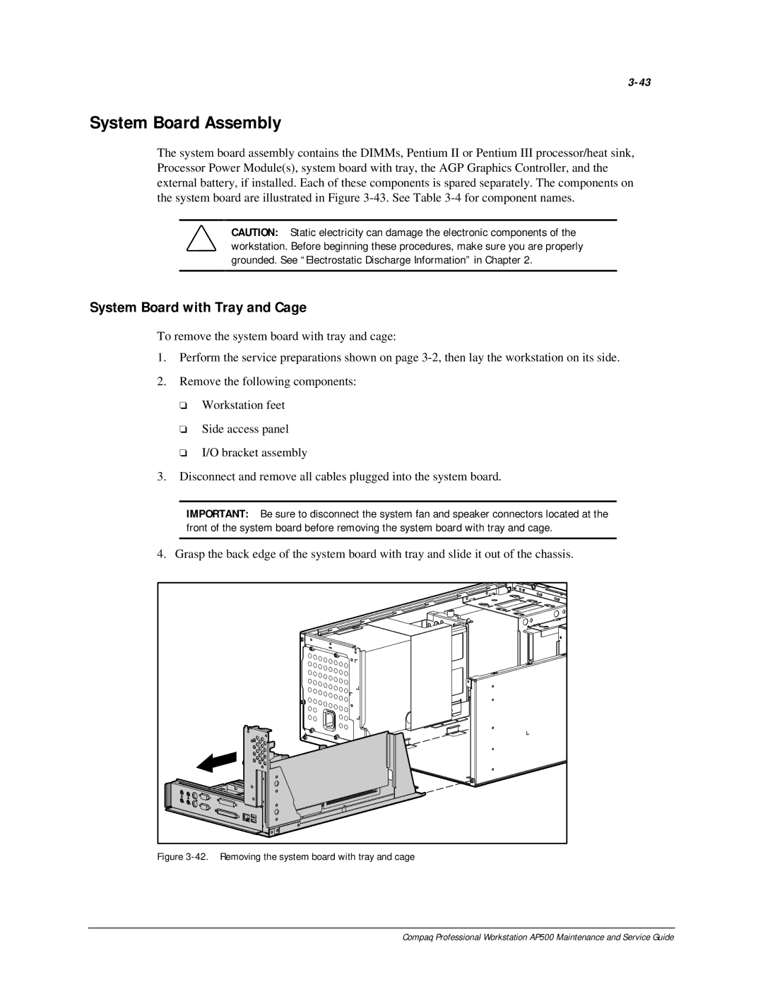
4. Grasp the back edge of the system board with tray and slide it out of the chassis.
Figure 3-42. Removing the system board with tray and cage
Compaq Professional Workstation AP500 Maintenance and Service Guide