Manuals
/
Compaq
/
Computer Equipment
/
Computer Accessories
Compaq
AP500
manual
System Components, 2Illustrated Parts Catalog
Models:
AP500
1
11
179
179
Download
179 pages
479 b
8
9
10
11
12
13
14
15
Troubleshooting
Install
Parts list
Error codes
Connector and Icon Pin Signal
Password
Symbols in Text
Warranty
Dimension
Power Problems
Page 11
Image 11
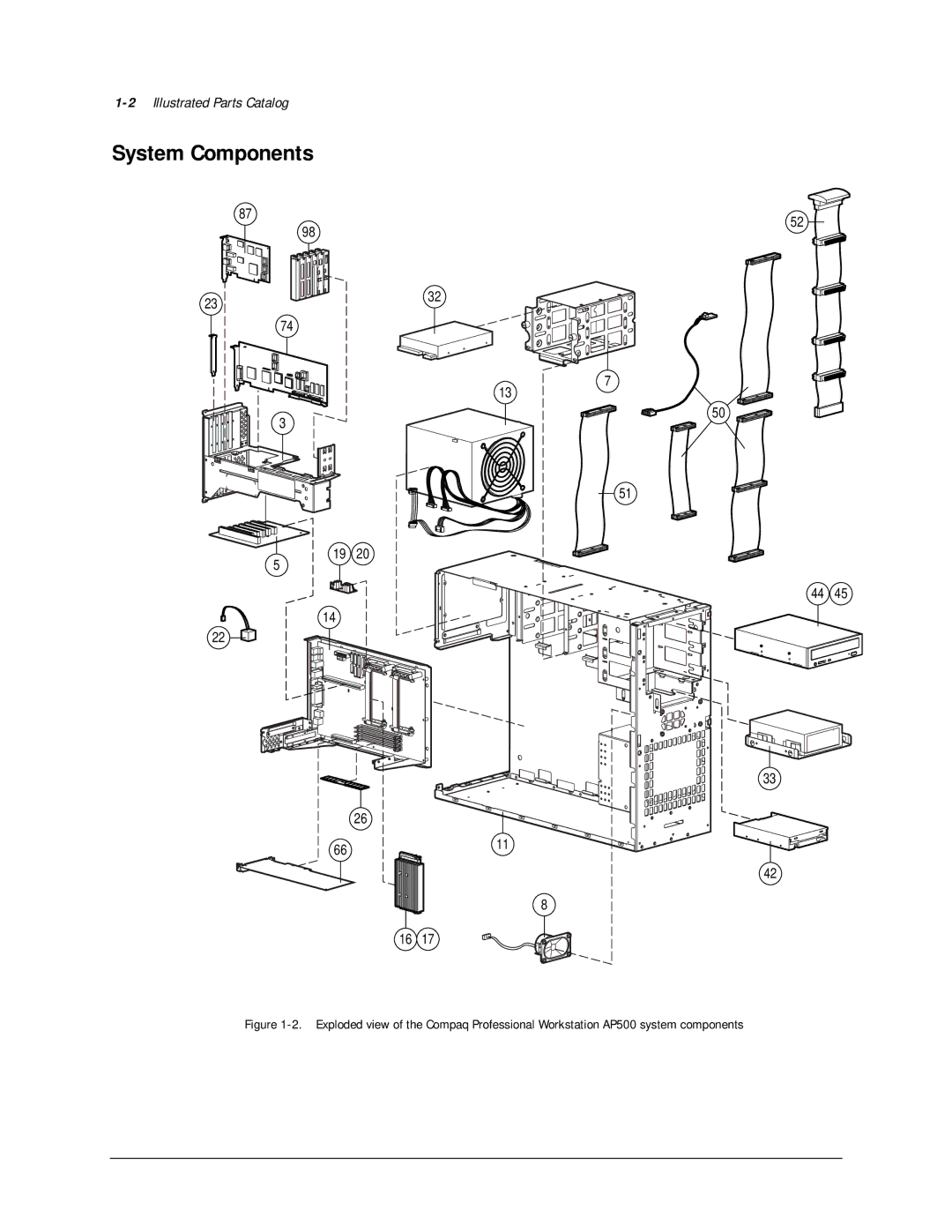
1-2
Illustrated Parts Catalog
System Components
87
52
98
23
32
74
7
13
50
3
51
19 20
5
44 45
14 22
33
26
66
11
42
8
16 17
Figure
1-2.
Exploded view of the Compaq Professional Workstation AP500 system components
Page 10
Page 12
Page 11
Image 11
Page 10
Page 12
Contents
Professional Workstation AP500
Second Edition March Part Number Spare Part Number
Contents
Removal and Replacement Procedures
Diagnostic Tools
System Security
Diagnostic Tools
Index
Vii
Text Conventions
Symbols on Equipment
Symbols in Text
Telephone Numbers
Where to Go for Additional Help
Other Information Sources
Mechanical Parts
Illustrated Parts Catalog
2Illustrated Parts Catalog
System Components
Reference Description Spares
Spares Parts List
Compaq Professional Workstation AP500 Spares Parts List
Reference Description
Compaq Professional Workstation AP500 Spares Parts List
4Illustrated Parts Catalog
Cable Kits
Reference
Description Spares
6Illustrated Parts Catalog
Software
Compaq Technician Notes
Service Preliminaries
Preliminary Warnings and Cautions
2Service Preliminaries
Electrostatic Discharge Information
Equipment Symbols
Tools and Software Requirements
Warranty Information
4Service Preliminaries
Serial Number
Removal and Replacement Procedures
2Removal and Replacement Procedures
Service Preparations
Cable Lock
Workstation Feet
4Removal and Replacement Procedures
Loosening the thumbscrews and removing the side access panel
Side Access Panel
Front Bezel
6Removal and Replacement Procedures
Removing a blank drive bezel
Blank Drive Bezel
EMI/Cooling Shield
8Removal and Replacement Procedures
Removing the speaker
Speaker
10Removal and Replacement Procedures
Bracket Assembly
Replacing the I/O Bracket Assembly
Identifying the PCI and ISA Expansion Slots
12Removal and Replacement Procedures
Expansion Boards
PCI/ISA Slots
Removing a PCI or ISA Expansion Board
14Removal and Replacement Procedures
Removing a Symbios Wide Ultra2 PCI Scsi Controller
12. Removing an AGP graphics controller
16Removal and Replacement Procedures
13. Removing the card guide
Removing the Card Guide
Removing the Backplane Board
18Removal and Replacement Procedures
15. Removing the system fan
System Fan
16. Removing the fan from the bracket
20Removal and Replacement Procedures
Drive Positions
Mass Storage Devices
Component Description
22Removal and Replacement Procedures
Drive Positions
18. Locating the hardware screws
Hardware Screws
CD-ROM Drive or DVD-ROM Drive
24Removal and Replacement Procedures
Pull the drive completely out of the drive cage
Diskette Drive
26Removal and Replacement Procedures
Pull the diskette drive straight out
Removing a 7200 rpm Hard Drive from Bays 5 or
28Removal and Replacement Procedures
Remove the EMI/cooling shield
26. Removing a hard drive from the hard drive bracket
30Removal and Replacement Procedures
Removing a 10,000-rpm Hard Drive from Bays 5 or
27. Disconnecting the cables from the hard drive
28. Disconnecting the fan power cable
32Removal and Replacement Procedures
30. Removing the EMI/cooling shield
32. Removing a hard drive from the hard drive bracket
34Removal and Replacement Procedures
33. Disconnecting the power cable
Removing the Fan from a Hard Drive Installed Bays 5 or
34. Removing the fan
36Removal and Replacement Procedures
Removing a Hard Drive from the Removable Hard Drive Cage
36. Removing the removable hard drive cage
38Removal and Replacement Procedures
Reference Bay
Installing a Hard Drive in the Removable Hard Drive Cage
Removable Hard Drive Screw Holes
39. Inserting a hard drive in the removable hard drive cage
40Removal and Replacement Procedures
Scsi Cables
Scsi Cables and Guidelines
Scsi Guidelines for Optimizing Performance
Scsi Guidelines for Installing Scsi Devices
42Removal and Replacement Procedures
System Board with Tray and Cage
System Board Assembly
44Removal and Replacement Procedures
Reference Component
System Board Components
System Board Components
Dual Inline Memory Modules DIMMs
Important Guidelines for Dimm Installation
46Removal and Replacement Procedures
Doing so may damage the Dimm
Removing a Dimm
48Removal and Replacement Procedures
Processor and Heatsink Assembly
47. Removing the processor power module
Processor Power Module
50Removal and Replacement Procedures
Primary Processor Power Module Cable Insulator
Running Computer Setup
External Battery
52Removal and Replacement Procedures
Installing the Battery
Page
54Removal and Replacement Procedures
Power Switch Cable Assembly
Power Supply
51. Removing the power supply air baffle
56Removal and Replacement Procedures
Diagnostic Tools
2Diagnostic Tools
Power-On Self-Test Post
Message Beeps Probable Cause Recommended Action
Post Messages
Post Messages
Message Beeps Probable Cause
4Diagnostic Tools
Post Messages
Diskette Drive Type Mismatch in drive type
6Diagnostic Tools
Troubleshooting Minor Problems
Problem
Power Problems
Solutions for Power Problems
8Diagnostic Tools
Problem Possible Solution
Diskette Drive Problems
Solutions for Diskette Drive Problems
10Diagnostic Tools
Display Problems
Solutions for Display Problems
Solutions for Display Problems
Printer Problems
Solutions for Printer Problems
12Diagnostic Tools
Hard Drive Problems
Solutions for Hard Drive Problems
Solutions for Hardware Installation Problems
Hardware Installation Problems
14Diagnostic Tools
CD-ROM Drive and DVD-ROM Drive Problems
Solutions for CD-ROM and DVD-ROM Drive Problems
Solutions for Scsi Problems
Memory Problems
Scsi Problems
Solutions for Memory Problems
Problem Cause
Network Problems
Solutions for Network Problems
16Diagnostic Tools
ProblemCause
Solutions for Network Problems
Audio Hardware Conflicts
18Diagnostic Tools
Accessing the Compaq Utilities Menu
Compaq Setup and Diagnostics Utilities
20Diagnostic Tools
Creating a Diagnostics Diskette
Computer Setup Selection
Computer Setup
Using Computer Setup
Computer Setup Features
Task Computer Setup Selection
22Diagnostic Tools
Computer Setup Features
Select Computer Checkup Test
Computer Checkup Test
View System Information Inspect
24Diagnostic Tools
Managing a Diagnostics Partition
Diagnostic Error Codes
Microprocessor
Microprocessor Test Error Codes
26Diagnostic Tools
Error Code
Keyboard
Memory Test Error Codes
Keyboard Test Error Codes
Memory
Error Code Description Recommended Action
Parallel Printer Test Error Codes
Diskette Drive Test Error Codes
28Diagnostic Tools
Modem
Serial Test Error Codes
Modem Communications Test Error Codes
Serial Port
CD-ROM Drive IDE
CD-ROM Drive IDE Test Error Codes
Tape Drive Test Error Codes
30Diagnostic Tools
Video
Video Test Error Codes
Video Test Error Codes
32Diagnostic Tools
Audio
Network Interface Test Error Codes
Audio Test Error Codes
Error Code Description Recommended Action 3206-xx
Scsi Device Names
Scsi Error Codes
34Diagnostic Tools
Scsi Test Error Codes
Error Code Description
36Diagnostic Tools
Scsi Test Error Codes
Upgrading the ROM
Local ROM Upgrade
Remote ROM Flash
38Diagnostic Tools
Identifying keyboard lights
FailSafe Boot Block ROM
Num Caps Scroll Meaning and Required Action
40Diagnostic Tools
System requires Setup Password
Keyboard Lights
Compaq Insight Manager
Remote Capability
Silent Setup Command Line Interface
42Diagnostic Tools
Compaq Workstation SSD for Windows NT
Compaq Diagnostics for Windows NT
Feature Purpose How It Is Established
Security Features
Security Features
2System Security
Password Security
Establishing a Setup Password Using Computer Setup
Establishing a Power-On Password Using Computer Setup
4System Security
Entering a Power-On Password
Changing a Power-On or Setup Password
Deleting a Power-On or Setup Password
3 4 5
Clearing a Power-On or Setup Password
6System Security
Windows NT Workstation Password
National Keyboard Delimiter Characters
National Keyboard Delimiter Characters
Advanced Security Management
Re-enabling Diskette Boot or Diskette Write
8System Security
Re-enabling a Serial Port or Parallel Port
QuickLock/QuickBlank
Enabling QuickLock and QuickBlank
Enabling the Keyboard and Mouse Interface
Cable Lock Provision
Disabling the Keyboard and Mouse Interface
Jumper and Switch Information
System Board Configuration Jumper J5 Settings
Battery Jumpers
2Jumper and Switch Information
500/100 MHz
Switch Settings
SW1 Settings
450/100 MHz
32X Max CD-ROM Drive IDE
4Jumper and Switch Information
Hard Drives
Identifier Function
PowerStorm 300/AGP Graphics Controller
Physical and Operating Specifications
Metric
2Physical and Operating Specifications
System Unit
System Function
System Direct Memory Access DMA
System Interrupts
Hardware IRQ
Address Hex
4Physical and Operating Specifications
System Function Shipping Configuration
System I/O
EGA/VGA
System I/O
Memory Address Size System Function
6Physical and Operating Specifications
Memory Addresses
Input Specifications Low Range High Range
325W Power Supply
325W Power Supply Specifications
MB Diskette Drive
8Physical and Operating Specifications
Diskette Drive
MB ZIP Drive
Zip Drive
32X Max Tray-Load CD-ROM Drive IDE
10Physical and Operating Specifications
CD-ROM Drive
32X Max CD-ROM Drive IDE
6X Max DVD-ROM Drive
12Physical and Operating Specifications
DVD-ROM Drive
6X Max DVD-ROM Drive
Rpm drive 10K rpm drive
14Physical and Operating Specifications
GB Wide-Ultra Scsi Hard Drive
GB Wide-Ultra Scsi Hard Drive 7200 rpm
GB Ultra ATA Hard Drive
16Physical and Operating Specifications
GB Ultra ATA Hard Drive 7200 RPM
Drive Configuration Drive Performance
Performance Criteria
18Physical and Operating Specifications
GB Wide Ultra2 Hard Drive 10,000 RPM
Value
Audio System
Compaq Enhanced Keyboard Dimensions Metric
Audio System
Keyboard
Mouse
20Physical and Operating Specifications
Button Mouse Dimensions Metric
Colors Supported Rate
Graphics Controllers
GLoria Synergy+ Graphics Controller Maximum Color Support
Maximum Refresh
Colors Maximum Display Area
22Physical and Operating Specifications
Resolutions Colors Maximum Refresh Rate Hz
Horizontal Refresh Rate kHz Vertical Refresh Rate Hz
Millennium G200 Graphics Controller Maximum Color Support
24Physical and Operating Specifications
Resolutions Colors
Ethernet Network Interface Controller NIC
RJ-45 Network Cable Specifications
Network Controller
Physical Location
External Connectors
Reference Connector
Reference Connector Function
2External Connectors
External Connectors
Keyboard
Connector and Icon Orange Pin Signal
Connector and Icon Green Pin Signal
Pin Assignments
Parallel Interface
4External Connectors
Connector and Icon Pin Signal
Serial Interfaces
Connector and Icon
Monitor
6External Connectors
Pin Signal
Universal Serial Bus USB
Ethernet RJ-45
8External Connectors
Scsi Connector
Headphone Connector
Line-In Connector
Line-Out Connector
Microphone Connector
Index
Index-2
Index-3
Index-4
Index-5
Index-6
Index-7
Index-8
Index-9
Index-10
Index-11
Index-12
Top
Page
Image
Contents