3-10 Removal and Replacement Procedures
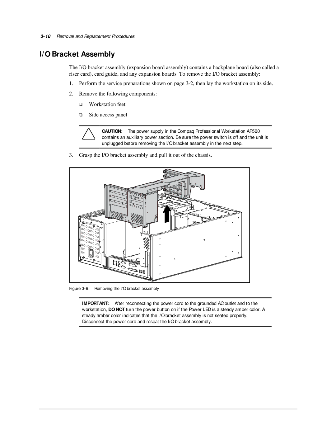
I/O Bracket Assembly
The I/O bracket assembly (expansion board assembly) contains a backplane board (also called a riser card), card guide, and any expansion boards. To remove the I/O bracket assembly:
1.Perform the service preparations shown on page
2.Remove the following components:
❏Workstation feet
❏Side access panel
CAUTION: The power supply in the Compaq Professional Workstation AP500 contains an auxiliary power section. Be sure the power switch is off and the unit is unplugged before removing the I/O bracket assembly in the next step.
3.Grasp the I/O bracket assembly and pull it out of the chassis.